
Twin skeg ship

A technology of skeg and fin plate, which is applied in the field of double skeg boats, can solve the problems of not being applicable to double skeg boats, and achieve the effect of increasing wake revenue and improving propulsion efficiency

Inactive Publication Date: 2011-04-13
MITSUBISHI HEAVY IND LTD
View PDF8 Cites 8 Cited by
  • Summary
  • Abstract
  • Description
  • Claims
  • Application Information

AI Technical Summary

Problems solved by technology

[0007] Therefore, in the past, on the opposite side of improving the propulsion performance of the ship, the reaction fins that constitute resistance in the water cannot be applied to the double skeg ship.

Method used


Image

  • Twin skeg ship
  • Twin skeg ship
  • Twin skeg ship

Examples


no. 1 approach

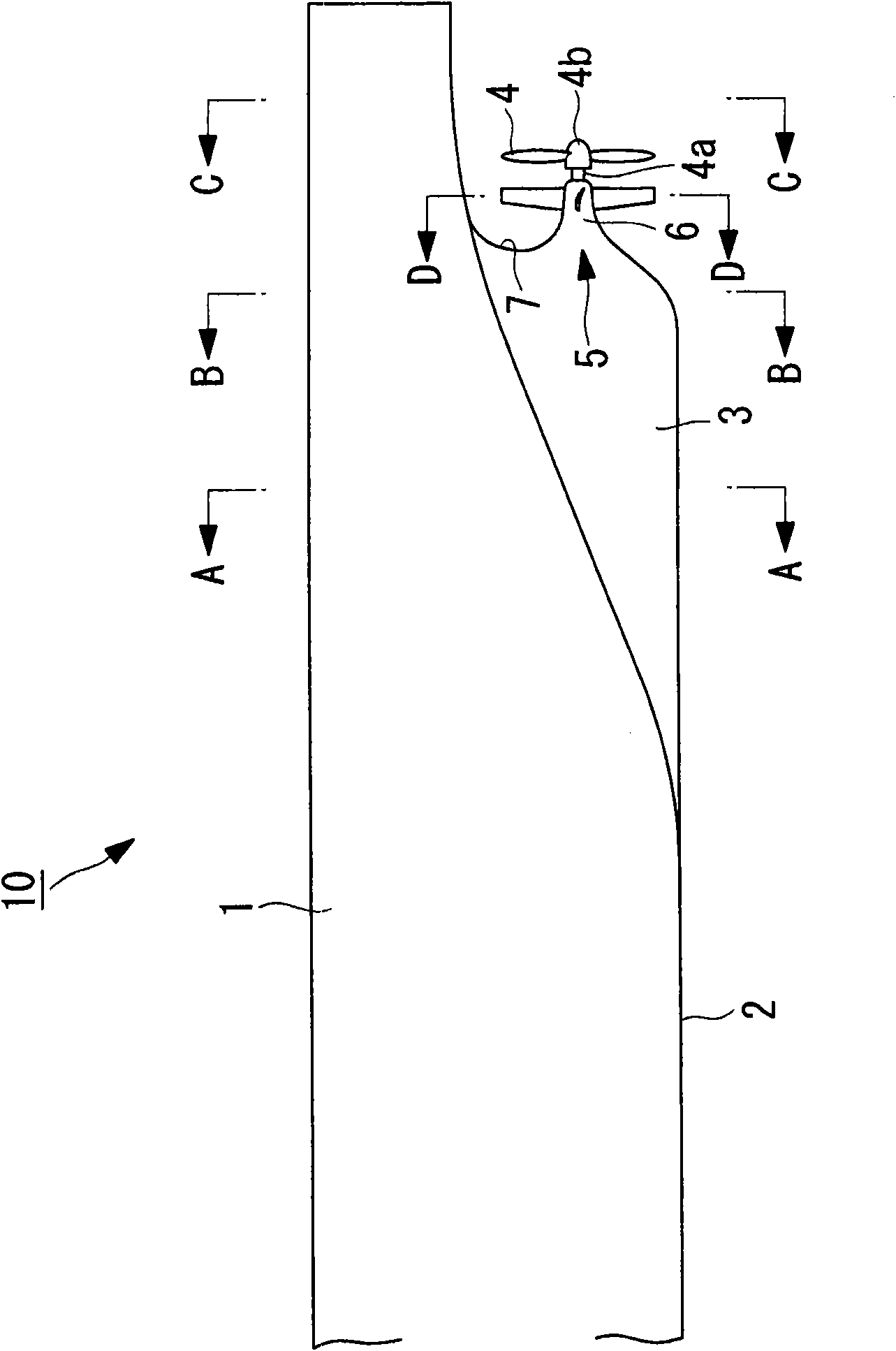
[0044] figure 1 It is the left side view seen from the port side of the stern side of the twin-skeg ship 10 of this embodiment, figure 1 The reference numeral 1 is the hull, the reference numeral 2 is the bottom, the reference numeral 3 is the skeg, the reference numeral 4 is the propeller (propeller wing), the reference numeral 4a is the propeller shaft, and the reference numeral 5 is the reaction fin . In addition, in order to realize the simplification of the drawing, the rudder is in figure 1 Not indicated in.

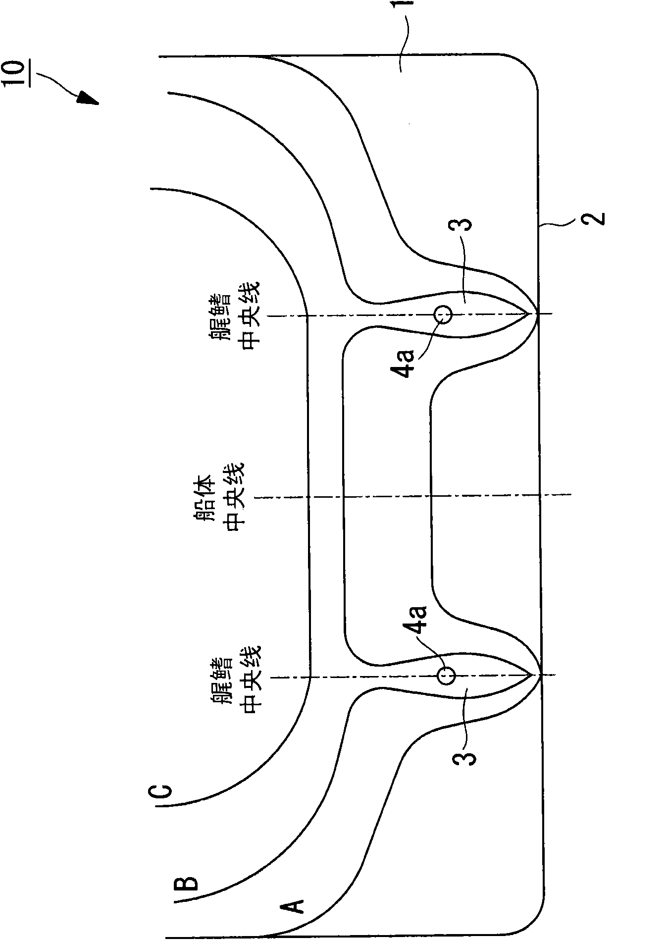
[0045] figure 2 yes means figure 1 The shown hull 1 is shown along A-A to line of sight, B-B to line of sight and C-C to the line of sight of the section cut off in the ship width direction, each section corresponding to A-A line of sight, B-B line of sight and C-C line of sight is given an appended Diagram labeled A, B, C. Such as figure 2 As shown, the twin-skeg ship 10 has a pair of left and right skegs 3 protruding downward from the ship bottom 2 const...


PUM


Abstract

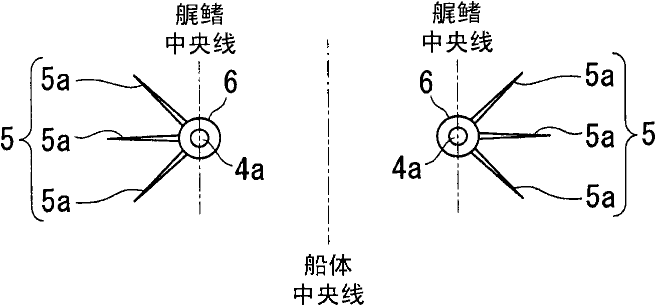
Disclosed is a twin skeg ship of which propulsion performance (propulsion efficiency) can be further enhanced. The twin skeg ship (10) is provided with a pair of right and left skegs (3) on the bottom (2) of the ship at the stern. In such a range as the flow just before a propeller (4) fixed to the skeg (3) through a propeller shaft (4a) has a component in the same direction as the rotational direction of the propeller (4), a reaction fin (5) consisting of a plurality of fins (5a) is provided to extend radially from a bossing (6) bonded to a stern frame (7) located at the rear end of the skeg (3) or from a fin boss provided on the bossing (6).

Description

technical field [0001] The present invention relates to a double skeg boat in which propeller shafts are supported on a pair of left and right skegs provided on the bottom of the stern. Background technique [0002] Conventionally, there is known a double-skeg boat in which a pair of left and right propeller shafts are supported by skegs integrated with the hull, and a tunnel-shaped bottom recess is formed between the left and right skegs (for example, refer to Patent Document 1). [0003] On the other hand, a reaction fin is proposed as a propulsion performance improving device (a device for increasing ship speed using the same horse power) equipped on a ship to improve the propulsion performance of the ship (for example, refer to Patent Document 2). [0004] Patent Document 1: Japanese Patent Application Laid-Open No. 8-133172 [0005] Patent Document 2: Japanese Patent Application Laid-Open No. 5-185986 [0006] In addition, in a double skeg ship (especially a double sk...

Claims


Application Information

Patent Timeline
Patent Type & Authority Applications(China)
IPC IPC(8): B63B1/08B63H5/16
CPCB63B1/08Y02T70/127B63H5/16Y02T70/128Y02T70/10
Inventor 坂本利伸
Owner MITSUBISHI HEAVY IND LTD
Learn More