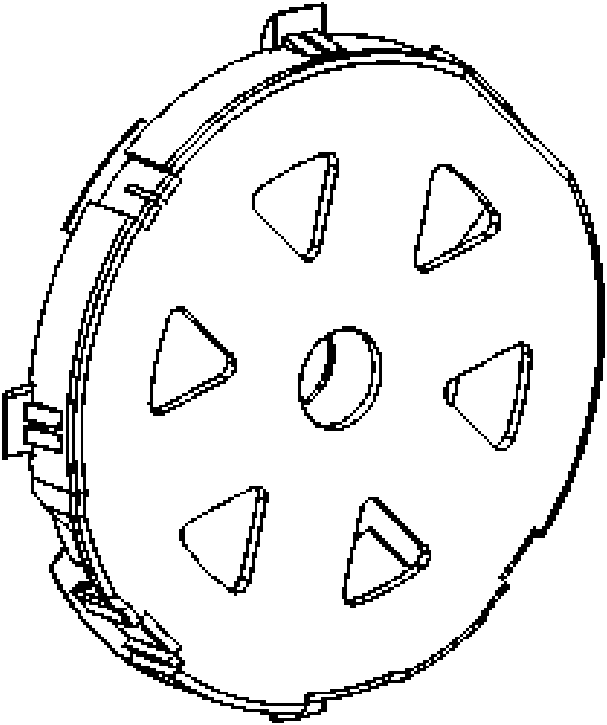
Dust collector reel

A technology of wire reels and vacuum cleaners, which is applied in the direction of electrical components, cable arrangement between relative moving parts, and cable installation. It can solve the problems of poor power line rotation and vacuum cleaners cannot stabilize the return line at a uniform speed, and achieve constant output. Uniform force and pulling force

Inactive Publication Date: 2011-04-20
LG ELECTRONICS (TIANJIN) APPLIANCES CO LTD
View PDF0 Cites 0 Cited by
  • Summary
  • Abstract
  • Description
  • Claims
  • Application Information

AI Technical Summary

Problems solved by technology

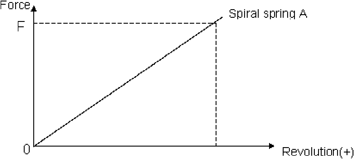
However, the coil spring structure of the vacuum cleaner cord reel in the prior art has the following disadvantages. When the user pulls out the power cord, the pulling force of the number of turns of the cord reel is proportional to the pulling force. Fast; while the winding wheel is in the process of returnin

Method used


Image

  • Dust collector reel
  • Dust collector reel
  • Dust collector reel

Examples


Example Embodiment

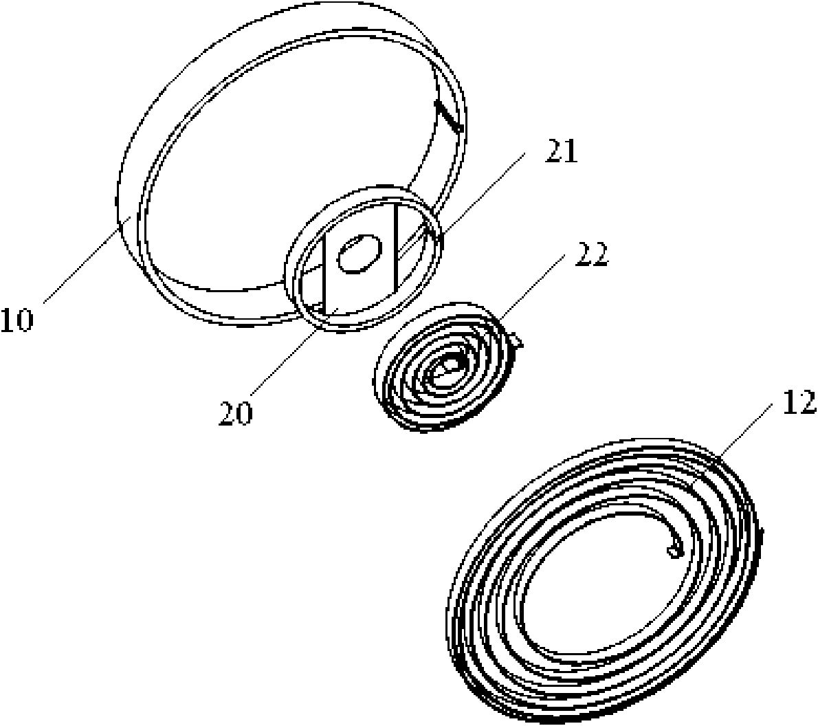
[0028] image 3 It is a three-dimensional exploded schematic diagram of the present invention provided with an auxiliary driving mechanism; Figure 4 It is a three-dimensional combined schematic diagram of the present invention provided with an auxiliary driving mechanism; Figure 5 It is a schematic plan view of the present invention provided with an auxiliary driving mechanism. Embodiment 1: Taking a main driving mechanism and an auxiliary driving mechanism horizontally arranged as an example for description, the auxiliary driving mechanism includes a main driving mechanism 10 and a first auxiliary driving mechanism 20 which are arranged coaxially and horizontally, two of which are The coil springs in the drive mechanism are connected in series and arranged concentrically. The diameter of the coil spring of the main drive is larger than the diameter of the coil spring in the auxiliary drive mechanism. The coil spring 12 of the main drive mechanism 10 is clamped on the coil spri...

Example Embodiment

[0029] Image 6 It is a three-dimensional exploded schematic diagram of the present invention with two auxiliary driving mechanisms; Figure 7 It is a schematic plan view of the present invention with two auxiliary driving mechanisms. Embodiment 2: Taking two auxiliary driving mechanisms horizontally arranged as an example for description, the reel includes a main driving mechanism 10, a first auxiliary driving mechanism 20 and a second auxiliary driving mechanism 30 which are arranged coaxially and horizontally. The coil springs in the mechanism are connected in series and arranged concentrically. The diameter of the coil spring in the main drive mechanism is the largest, the diameter of the coil spring in the second auxiliary drive mechanism is second, and the diameter of the coil spring in the first auxiliary drive is the smallest, so The reel box includes a main drive mechanism 10, a first auxiliary drive mechanism 20, and a second auxiliary drive mechanism 30 which are coax...


PUM


Abstract

The invention discloses a dust collector reel, which comprises a center shaft, a reeling wheel, a main reeling wheel driving mechanism consisting of a coil spring and a coil spring shell, and an auxiliary driving mechanism coaxial with the driving mechanism, wherein the auxiliary driving mechanism comprises a coil spring, a coil spring shell and a clamping groove, the coil spring of the auxiliary driving mechanism is connected in series with the coil spring of the driving mechanism, and the rotating directions of all the coil springs are consistent. The dust collector reel has the advantages that: two or more coil springs are adopted, and the coil springs rotate when a power wire is pulled out, so the extreme value of the pull-out force is reduced, the pull-out force is uniform and the constant output force is realized.

Description

technical field [0001] The invention relates to a vacuum cleaner; in particular, it relates to a coil spring structure of a cord reel for a vacuum cleaner with uniform tension. Background technique [0002] Generally, a vacuum cleaner is a device that uses a vacuum to generate suction to inhale air, make the air flow through various filters, filter foreign objects in the air, and clean the room. [0003] Generally speaking, a vacuum cleaner mainly includes a suction device and a suction pipeline. The suction device mainly formed by a motor and a fan is arranged in the body. The suction pipeline includes a suction head and a suction pipe. The suction head has a downward opening. The suction port communicates with the air inlet of the fan inside the body through the telescopic pipe and the flexible pipe of the suction pipe. When the vacuum cleaner is running, the motor drives the impeller of the fan to rotate at a high speed, exhausting the air in the vacuum cleaner, forming ...

Claims


Application Information

Patent Timeline
IPC IPC(8): A47L9/26
Inventor 孟庆琛任光智
Owner LG ELECTRONICS (TIANJIN) APPLIANCES CO LTD
Why Eureka
Try Eureka