
Traction structure of freight elevator based on 6 to 1 suspension way

A technology of elevator traction and suspension, which is applied to elevators in buildings, hoisting equipment in mines, elevators, etc., can solve the problems of uneven pulling force of steel wires and easy concentration of stress, so as to increase the distribution width and improve The effect of uniform tension and reduced stress concentration

Pending Publication Date: 2021-01-05
中科西奥电梯有限公司
View PDF0 Cites 0 Cited by
  • Summary
  • Abstract
  • Description
  • Claims
  • Application Information

AI Technical Summary

Problems solved by technology

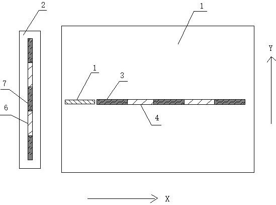
[0003] The traditional traction elevator with 6:1 suspension method has the following layout due to the layout of anti-rope pulley and guide pulley figure 2 As shown, the main problem is that the lifting force of the steel wire on the car is not uniform enough, and the stress is easily concentrated.

Method used


Image

  • Traction structure of freight elevator based on 6 to 1 suspension way
  • Traction structure of freight elevator based on 6 to 1 suspension way

Examples


Embodiment

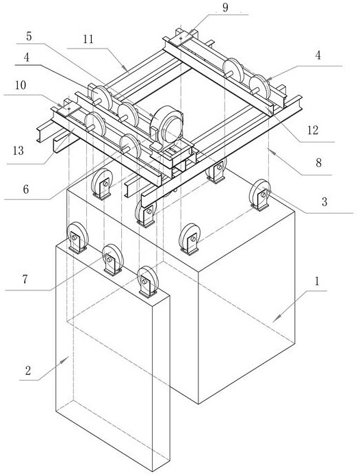
[0019] Such as figure 1 As shown, a freight elevator traction structure based on the 6:1 suspension method includes 3 sets of car anti-rope pulleys, 4 sets of car guide wheels, 2 counterweights, counterweight anti-rope pulley sets, and counterweight guide wheels Group, main load-bearing beam 11, car auxiliary beam 12.

[0020] In this embodiment, the 3 groups of car reversing sheaves include a first pair of car reversing sheaves 3 , a second pair of car reversing sheaves 3 , and a third pair of car reversing sheaves 3 .

[0021] Parallel between the first pair of car reversing sheaves 3, the second pair of car reversing sheaves 3, and the third pair of car reversing sheaves 3, they are evenly arranged at the front end, the middle end, and the rear end of the car 1 top.

[0022] The first pair of car reversing sheaves 3, the second pair of car reversing sheaves 3, and the third pair of car reversing sheaves 3 all include two car reversing sheaves 3, and the car reversing shea...


PUM


Abstract

The invention discloses a traction structure of a freight elevator based on 6 to 1 suspension way. The traction structure comprises an elevator cabin, an elevator cabin suspension sheave group, an elevator cabin guiding wheel group, a counterweight, a counterweight suspension sheave group, a counterweight guiding wheel group, and a traction machine which is arranged in a machine room, wherein theelevator cabin suspension sheave group comprises a first pair of elevator cabin suspension sheave, a second pair of elevator cabin suspension sheave and a third pair of elevator cabin suspension sheave, and the first pair of elevator cabin suspension sheave, the second pair of elevator cabin suspension sheave and the third pair of elevator cabin suspension sheave are separately composed of at least two elevator cabin suspension sheaves which are rotatably arranged on the top of the elevator cabin; the elevator cabin guiding wheel group comprises a first pair of elevator cabin guiding wheel group and a second pair of elevator cabin guiding wheel group, and the first pair of elevator cabin guiding wheel group and the second pair of elevator cabin guiding wheel group are separately composed of at least two elevator cabin guiding wheels; one end of a steel rope is fixed to a counterweight rope head, bypasses the first counterweight suspension sheave, one counterweight guiding wheel, the second counterweight suspension sheave, another counterweight guiding wheel, the third counterweight suspension sheave, the traction machine, the first pair of elevator cabin suspension sheave, the first elevator cabin guiding wheel, the second pair of elevator cabin guiding wheel and the third pair of elevator cabin suspension sheaves, and then is fixed to the elevator cabin rope head.

Description

technical field [0001] The invention relates to the technical field of elevators, in particular to a freight elevator traction structure based on a 6:1 suspension mode. Background technique [0002] Since the permanent magnet synchronous traction machine is widely used in modern elevators, the permanent magnet synchronous traction machine is superior to the traditional worm gear traction machine in terms of manufacturing cost, energy saving, and maintenance convenience. However, the torque of the permanent magnet synchronous traction machine is smaller than that of the worm gear traction machine. If it reaches the high torque of the worm gear traction machine, the cost of the permanent magnet synchronous traction machine will be very high, so now it is popular to use the method of increasing the suspension ratio. It is a scheme to increase the linear velocity of the elevator wire rope and reduce the tension of the wire rope, thereby reducing the torque of the traction machin...

Claims


Application Information

Patent Timeline
IPC IPC(8): B66B11/04B66B11/00B66B7/06B66B17/12
CPCB66B11/043B66B11/0065B66B7/06B66B17/12
Inventor 王小平
Owner 中科西奥电梯有限公司
Learn More