
Remote control model locomotive

A locomotive and model technology, applied in the field of remote control model locomotives, can solve problems such as inability to respond to rear wheels in real time, strain, abnormal shaking of model locomotives, etc.

Inactive Publication Date: 2011-04-20
ANDERSON MODEL
View PDF4 Cites 3 Cited by
  • Summary
  • Abstract
  • Description
  • Claims
  • Application Information

AI Technical Summary

Problems solved by technology

However, it should be noted that when the operator brakes the remote control model locomotive from high-speed travel or performs deceleration coasting, theoretically the clutch set has been reduced to a low speed due to the rear wheel speed, and the centrifugal force of the clutch set should slow down immediately. contract and break away from the inner wall of the flywheel; but in practice, the clutch set cannot react in real time to the situation that the rear wheel has decelerated or braked, and immediately separates from the flywheel set. Therefore, the clutch set will actually still temporarily stick (about 1 within seconds) flywheel phenomenon
Therefore, due to the viscous inertial impulse or torque from the flywheel set in the planetary gear set inside the remote control model locomotive, the multiple planetary gears in the planetary gear set and the toothed disc will instantly resist each other in torque, which will cause the model locomotive to be manipulated differently. Normal shaking affects the stability of the vehicle body control; moreover, after a long period of operation, the planetary gear set is prone to strain between the multiple planetary teeth and the ring plate, resulting in tooth collapse and damage

Method used


Image

  • Remote control model locomotive
  • Remote control model locomotive
  • Remote control model locomotive

Examples


Embodiment Construction

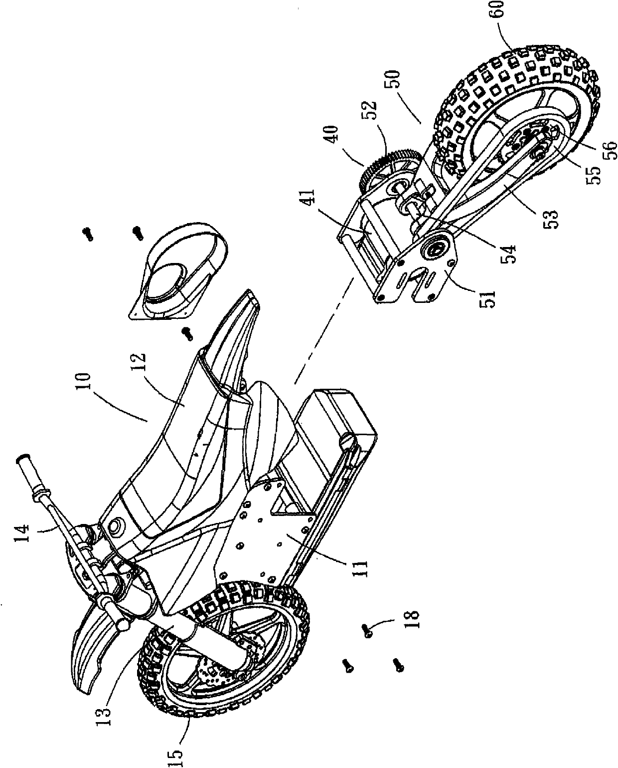
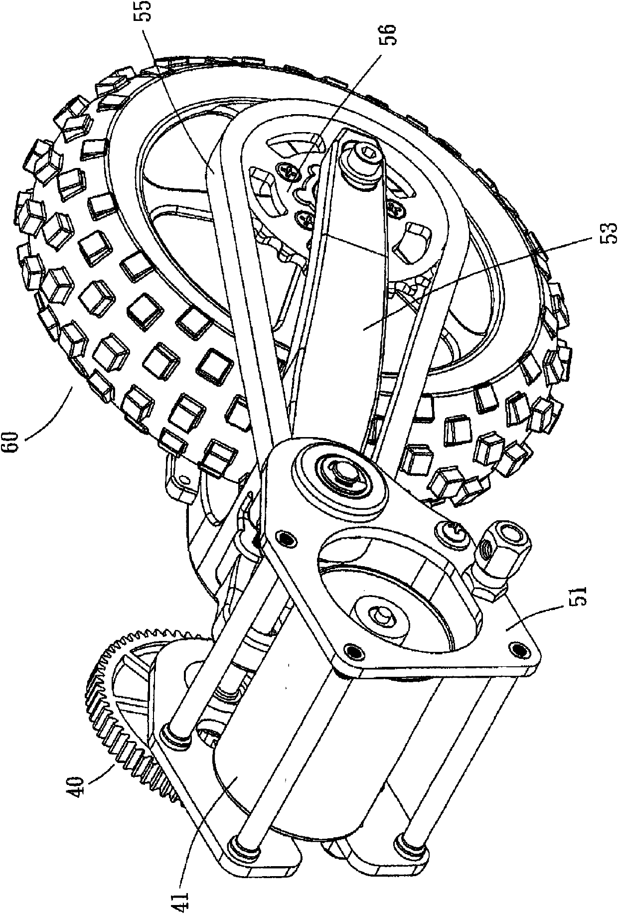
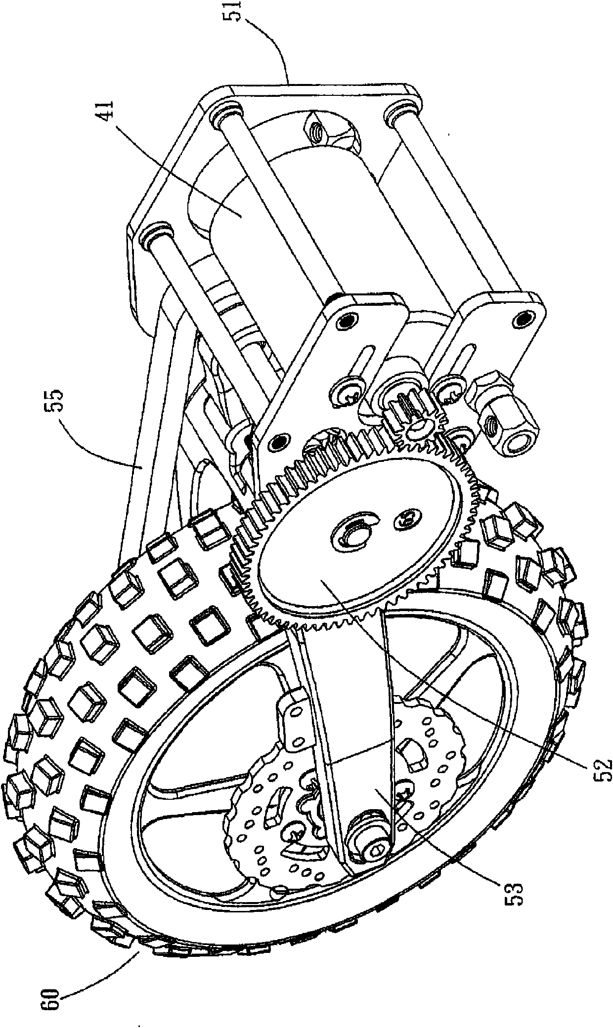
[0043] see Figure 1 to Figure 6 As shown, a remote control model locomotive provided by the embodiment of the present invention includes a front body 10, a rear body 50 and a power output device 40, wherein the front body 10 has a front frame 11, and the front frame The upper end of 11 is a cushion 12, a rider (not shown on the figure) can be installed on the cushion 12 in practice, and the front frame 11 and the cushion 12 are provided with a front suspension 13 and a steering faucet 14 in the common front, and the front suspension 13 below A front wheel 15 is provided; the rear body 50 is integrated with the front body 10 in a detachable manner. During assembly, the rear vehicle frame 51 of the rear vehicle body 50 is just fitted with the front vehicle frame 11 of the front vehicle body 10 and combined with each other by a plurality of screws 18 to form a group. The rear end of the rear frame 51 of the rear vehicle body 50 is a rear suspension 53 and a rear wheel 60 . The...


PUM


Abstract

The invention discloses a remote control model locomotive comprising a locomotive body, front and rear wheels arranged on a front section and a rear section of the locomotive body and a power output device, wherein each rear wheel comprises a fixed rod, a rim set, a planetary gear set, a unidirectional rotating piece, a clutch set and a fly wheel set, wherein the rim set is used for the fixed rod to pass through and to be positioned and driven by the power output device to rotate; the planetary gear set comprises a fluted disc and a plurality of planetary gears; a shaft hole is arranged in the center of the fluted disc and used for the fixed rod to pass through; the planetary gears are meshed and rotate around the fluted disc; the unidirectional rotating piece passes through and is arranged between the fixed rod and the shaft hole of the fluted disc and unidirectionally reversely rotates when being used for braking the fluted disc to receive the external viscous torque; the clutch set is connected with the planetary gears to synchronously rotate and expands outwards due to the centrifugal force during rotation at high speed; the fly wheel set is provided with a fly wheel body, is encircled on the outer circumferential edge of the clutch set and is expanded and braked by the clutch set to synchronously rotate at high speed; and the fly wheel body is provided with a plurality of depresses which are used for balance weight blocks with the same or less than the number of the depresses to be inserted into.

Description

technical field [0001] The invention relates to a remote-control model locomotive, in particular to a remote-control model locomotive with improved running stability of the vehicle body. Background technique [0002] Early remote control model locomotives such as U.S. Pat. No. 4,342,175 wireless remote control locomotives, U.S. Pat. No. 5,368,516 wireless remote control two-wheeled toy locomotives generally include a frame, and a front and rear wheels are respectively arranged on the length of the frame. The front and rear sections of the shaft are used to support the frame, wherein the front wheels are responsible for steering, and the rear wheels are driven by a power drive device to provide the power source for the locomotive to travel. However, the steering of the above-mentioned previous proposal adopts a gravity shift (gravity shift) control mechanism, so when the front wheels of the locomotive are turned, a large turning radius is usually required, so the controllabil...

Claims


Application Information

Patent Timeline
Patent Type & Authority Applications(China)
IPC IPC(8): A63H17/385
Inventor 陈汉村
Owner ANDERSON MODEL
Learn More