
circuit module

A technology of circuit modules and circuit substrates, applied in the direction of circuits, printed circuits, printed circuits, etc., can solve problems such as disconnection, and achieve the effect of suppressing dumping

Inactive Publication Date: 2015-09-23
MURATA MFG CO LTD
View PDF7 Cites 0 Cited by
  • Summary
  • Abstract
  • Description
  • Claims
  • Application Information

AI Technical Summary

Problems solved by technology

As a result, a disconnection may occur between the electronic component 502 and the circuit board 510

Method used


Image

  • circuit module
  • circuit module
  • circuit module

Examples


Embodiment Construction

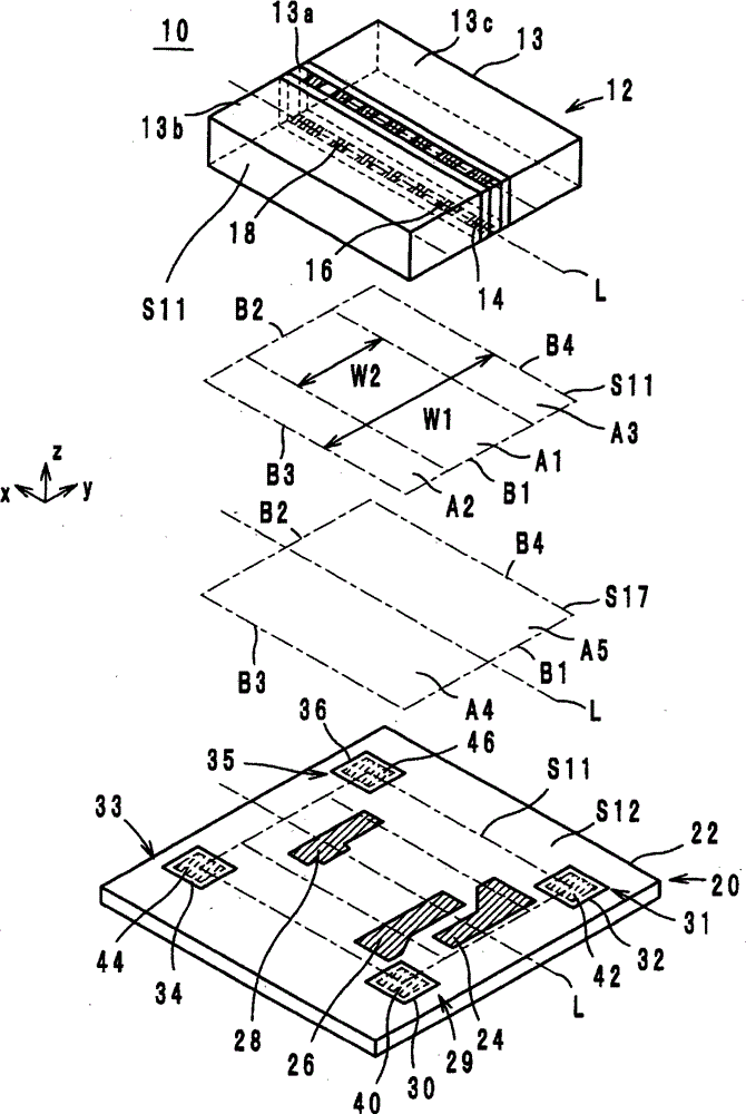
[0022] Hereinafter, a circuit module according to an embodiment of the present invention will be described with reference to the drawings.

[0023] (Structure of Circuit Module)

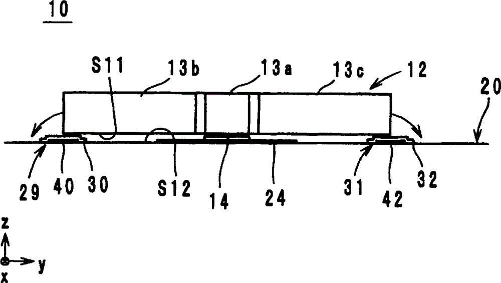
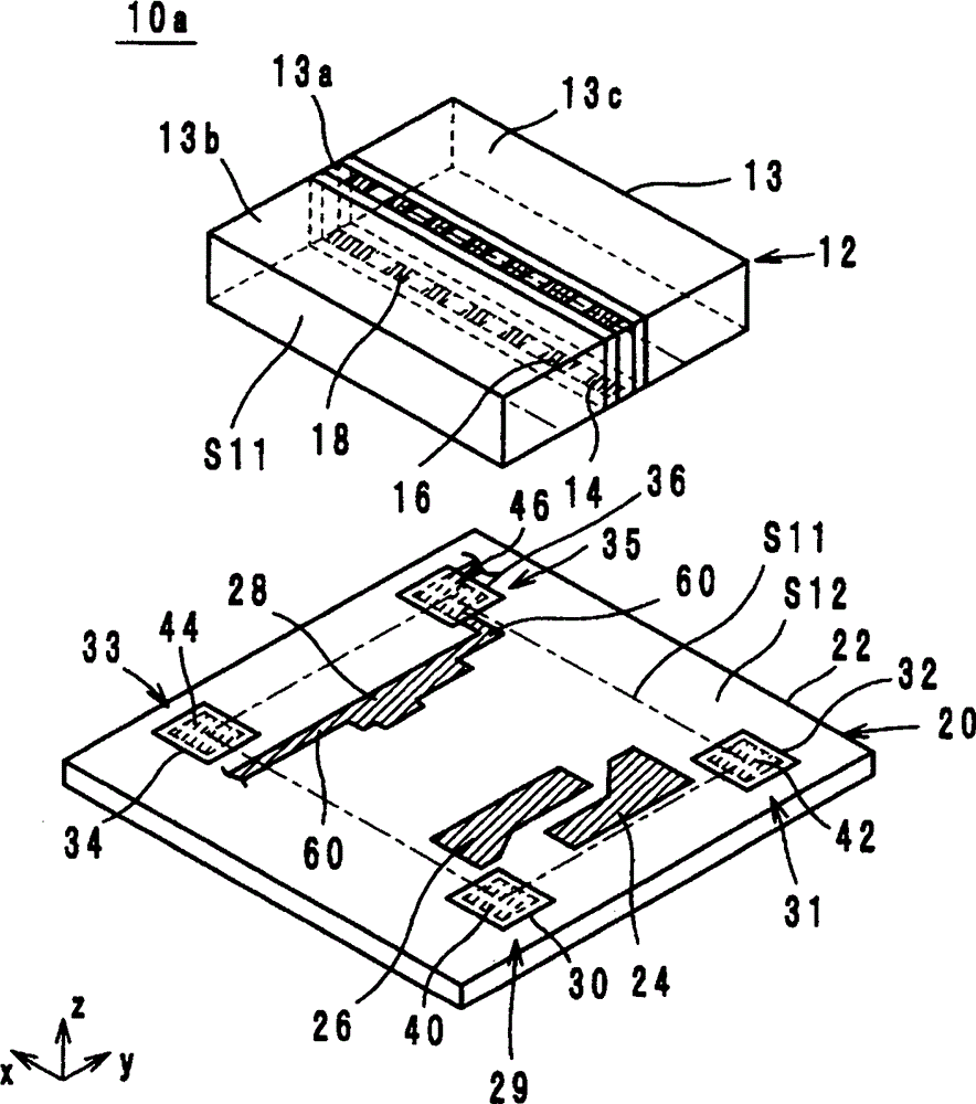
[0024] The configuration of a circuit module according to an embodiment of the present invention will be described below. figure 1 It is an exploded perspective view of the circuit module 10 . exist figure 1 In the above, the normal direction of the main surface of the circuit board 20 is defined as the z-axis direction, and the direction along the long side of the electronic component 12 is defined as the x-axis direction when the electronic component 12 is viewed from the z-axis direction. The direction of the short side of the electronic component 21 is defined as the y-axis direction.

[0025] The circuit module 10 is a so-called non-reciprocal circuit element, which has a characteristic of transmitting a signal only in a predetermined specific direction and not transmitting a signal in the ...


PUM


Abstract

An electronic component includes a component body including a mounting surface facing a circuit substrate, and a plurality of first external electrodes arranged on the mounting surface so as to extend between a first side and a second side of the mounting surface substantially parallel with each other and so as to be within a first region having a width that is substantially equal to half a length of the first side in a direction in which the first side extends. A circuit substrate includes a substrate body, a plurality of second external electrodes, arranged on a main surface of the substrate body, respectively connected to the plurality of the first external electrodes, and support units arranged to protrude from the main surface of the substrate body and such that the electronic component overlaps the support units outside the first region.

Description

technical field [0001] The present invention relates to a circuit module, and particularly relates to a circuit module configured by mounting electronic components on a circuit board. Background technique [0002] As a conventional circuit module, for example, a two-port nonreciprocal circuit element (hereinafter simply referred to as a nonreciprocal circuit element) described in Patent Document 1 is known. Hereinafter, the non-reciprocal circuit element described in Patent Document 1 will be described with reference to the drawings. Image 6 It is an exploded perspective view of the non-reciprocal circuit element 500 . Image 6 In the above, the normal direction of the main surface of the circuit board 510 is defined as the z-axis direction, and the direction along the long side of the electronic component 502 is defined as the x-axis direction when the electronic component 502 is viewed from the z-axis direction. The direction of the short side of the electronic component ...

Claims


Application Information

Patent Timeline
Patent Type & Authority Patents(China)
IPC IPC(8): H01L25/00
CPCH05K2201/2036H05K3/303H05K2201/083H05K2201/099H05K3/3431H05K2201/09781Y02P70/50
Inventor 高桥康弘
Owner MURATA MFG CO LTD
Learn More