Self-locking air pressure detection device
An air pressure detection and self-locking technology, which is applied in the direction of measuring devices, inflatable gas pressure measurement, and fluid pressure measurement, can solve the problems of being unable to meet the use requirements, the cost of electronic induction devices and their peripheral circuits, and the inability to be widely used. Compact structure, small size, avoiding the effect of frequent starting
- Summary
- Abstract
- Description
- Claims
- Application Information
AI Technical Summary
Problems solved by technology
Method used
Image
Examples
Embodiment 1
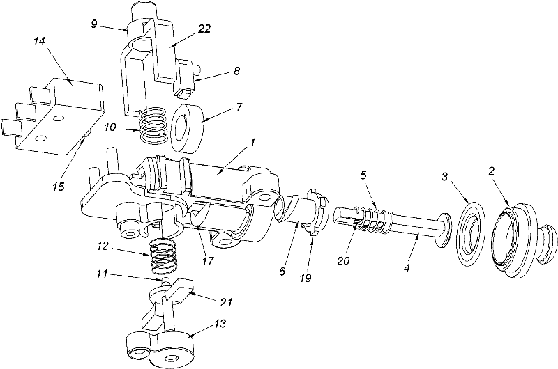
[0021] Such as figure 1 As shown, the self-locking air pressure detection device of this embodiment consists of a base body 1, an air pressure nozzle 2, an adhesive film 3, a push rod 4, a pressure spring 5, an adjusting coil 6, an adjusting nut 7, an adjusting rod 8, an unlocking button 9, Unlocking button stage clip 10, self-locking pressure rod 11, self-locking stage clip 12, self-locking pressure rod guide sleeve 13 and microswitch 14 constitute.
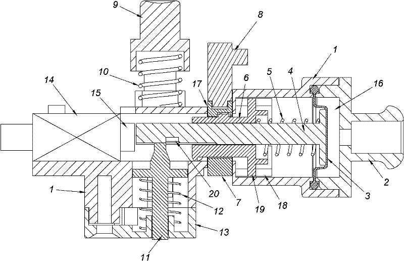
[0022] Such as figure 2 As shown, the micro switch 14 , the ejector rod 4 , the film 3 and the air nozzle 2 are all installed on the base 1 . A button 15 is provided on the micro switch 14 . The air pressure nozzle 2 presses the adhesive film 3 on the substrate 1 , and a pressure chamber 16 is formed between the air pressure nozzle 2 and the adhesive film 3 , and the adhesive film 3 is a deformable part of the pressure chamber 16 . One end of the ejector rod 4 is pressed against the rubber film 3 of the pressure chamber 16 t...
Embodiment 2
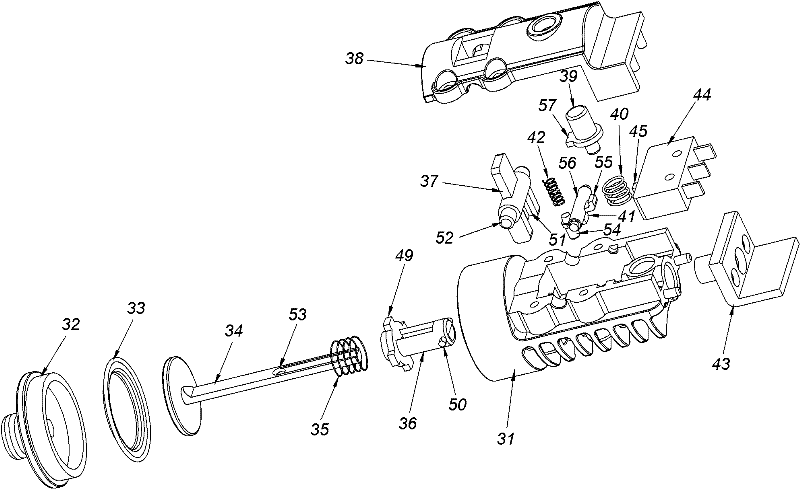
[0027] Such as image 3As shown, the self-locking air pressure detection device of this embodiment consists of a base body 31, an air pressure nozzle 32, an adhesive film 33, a push rod 34, a pressure spring 35, a top block 36, a shift lever 37, a gland 38, a reset button 39, a reset Button stage clip 40, self-locking stage bar 41, self-lock stage clip 42, tail cover 43 and micro switch 44 constitute. The gland 38 is matched with the base body 31 and serves as a part of the base body 31 .
[0028] Such as Figure 4 As shown, the ejector rod 34 , the adhesive film 33 , the air pressure nozzle 32 , the gland 38 and the tail cap 43 are all installed on the base body 31 . The micro switch 44 is installed between the pressing cover 38 and the tail cover 43 so as to realize connection and installation with the base body 31 . A button 45 is provided on the micro switch 44 . The air pressure nozzle 32 presses the adhesive film 33 onto the substrate 31 , a pressure chamber 46 is fo...
PUM
 Abstract
Description
Claims
Application Information
 - R&D
- Intellectual Property
- Life Sciences
- Materials
- Tech Scout
- Unparalleled Data Quality
- Higher Quality Content
- 60% Fewer Hallucinations
Browse by: Latest US Patents, China's latest patents, Technical Efficacy Thesaurus, Application Domain, Technology Topic, Popular Technical Reports.
© 2025 PatSnap. All rights reserved.Legal|Privacy policy|Modern Slavery Act Transparency Statement|Sitemap|About US| Contact US: help@patsnap.com


