

Compressor for refrigerator
A refrigerator compressor, compression pump technology, applied in the direction of compressors, irreversible cycle compressors, refrigerators, etc., can solve problems such as interference of household appliances, low work efficiency, large power grid loss, etc., and achieve the effect of improving the cooling speed.
- Summary
- Abstract
- Description
- Claims
- Application Information
AI Technical Summary
Problems solved by technology
Method used
Image

Examples
Embodiment 1
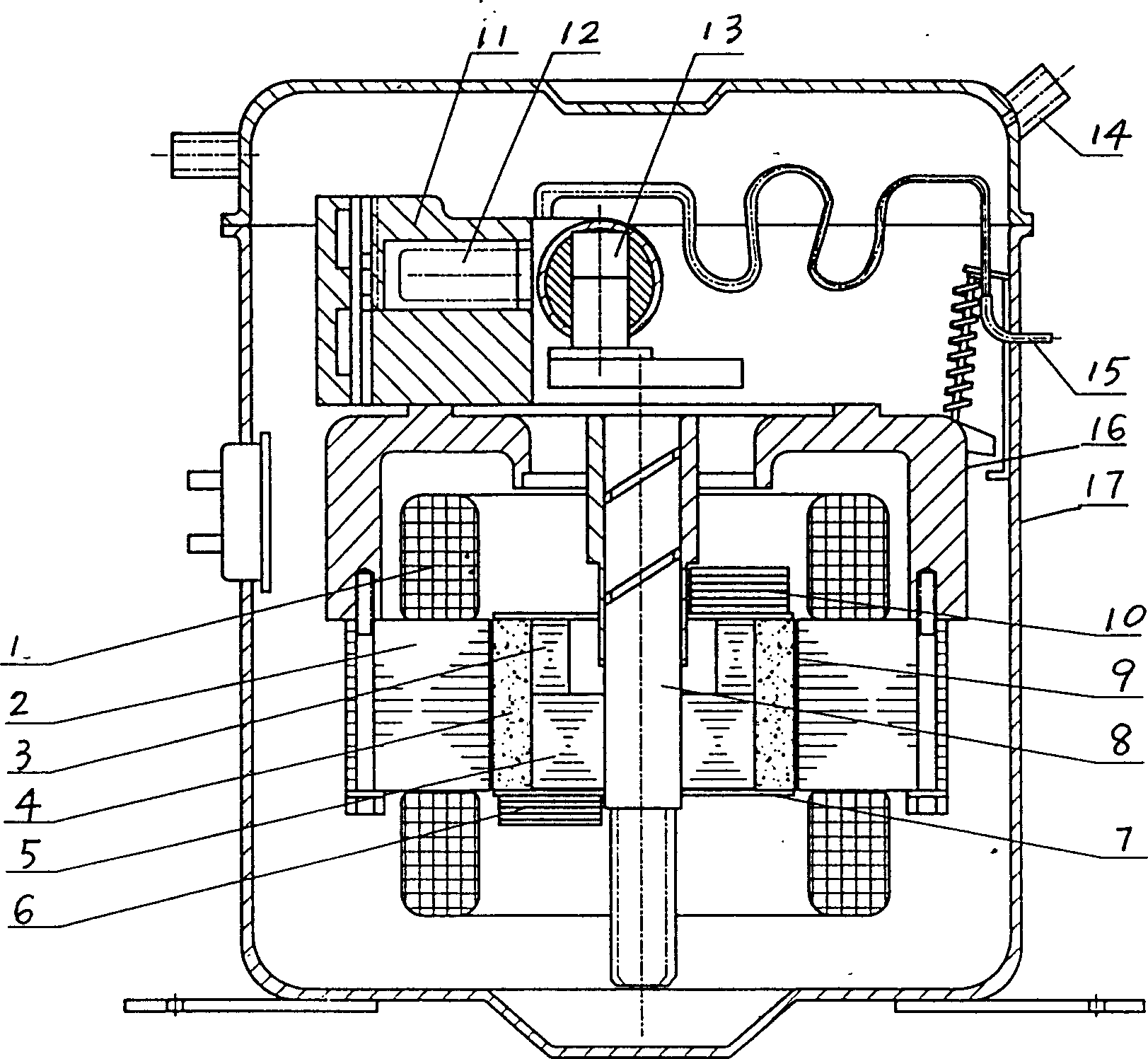
[0028] Example 1 ( figure 1 ):
[0029] The permanent magnet brushless DC motor used in this example includes a crankshaft 8, rotor cores 5 and 3 fixed on the crankshaft, tile-shaped magnetic steel 4 installed outside the rotor core, stator core 2, embedded in the stator core The stator winding 1 in the slot, the tile-shaped magnetic steel is covered with a stainless steel collar 9 that fixes it with the rotor core, and the tile-shaped magnetic steel adopts anisotropic ferrite whose magnetization direction is radially oriented Permanent magnets or NdFeB permanent magnets, the stator windings are three-phase windings, the stator three-phase windings are connected to a DC frequency conversion circuit, the rotor cores 3 and 5 are laminated silicon steel sheets, and semicircular The eccentric balance weights 6 and 10 are provided with a non-magnetic magnetic isolation plate 7 which can prevent the axial magnetic short circuit of the magnet steel 4 between the balance weight and t...
Embodiment 2
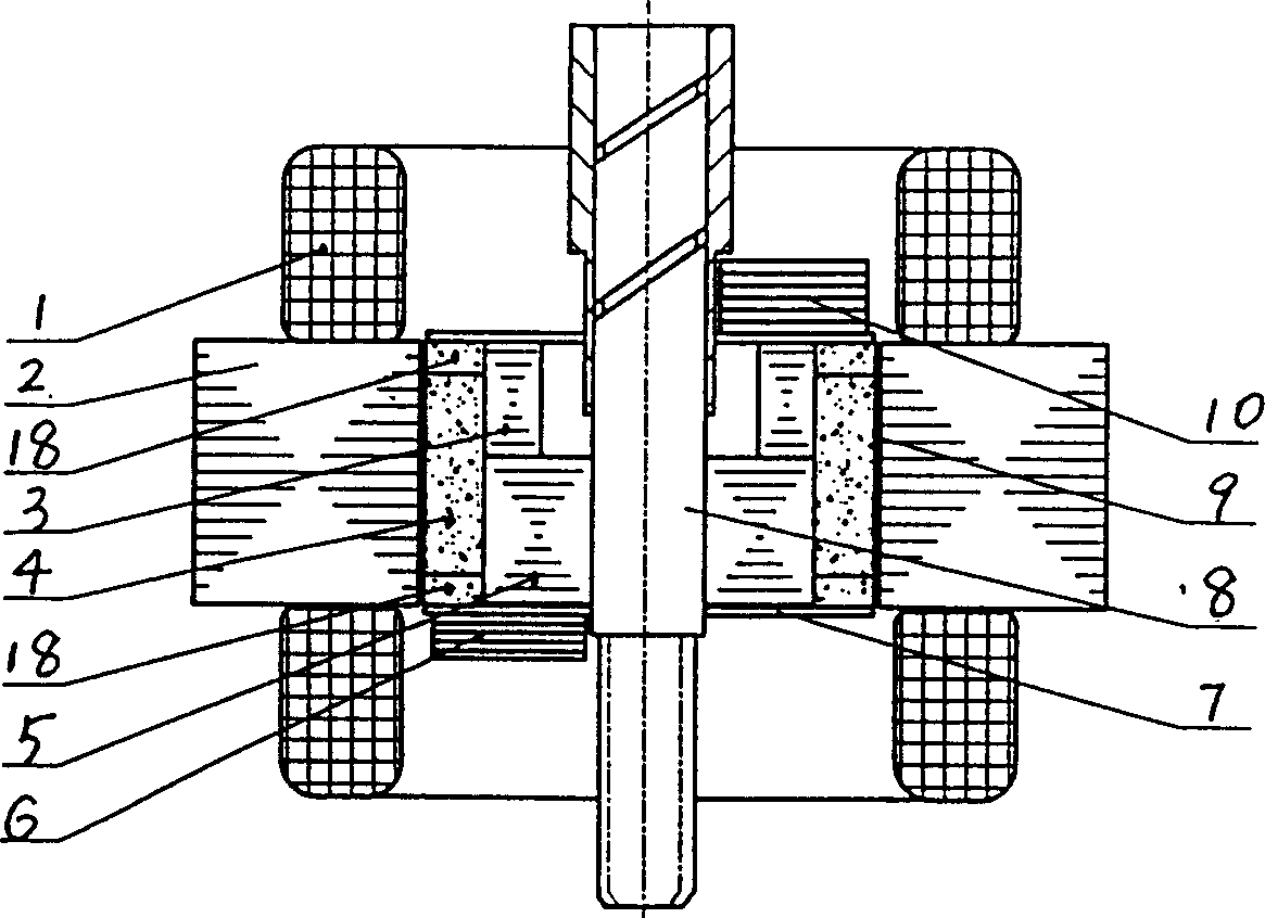
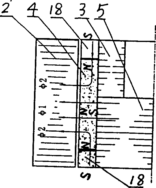
[0032] The rotor magnets of each pole in this example are composed of a radial magnet 4 and two tangential magnets 18 located at the two axial ends of the radial magnet 4 respectively. The radial magnets form the main poles, and the tangential magnets form the auxiliary poles.
[0033] As mentioned above, the present invention is provided with balance weights 6, 10 at both axial ends of the rotor iron core, which can solve the steering transition problem of the reciprocating motion of the piston by using the rotational inertia, although a magnetic isolation plate 7 is arranged between it and the magnetic steel, However, due to the small gap between the balance weight and the end face of the magnet, it is inevitable to short-circuit the magnetic circuit of some magnets, which increases the flux leakage of the motor, reduces the flux density of the air gap, and affects the output and quick response of the motor. And the structure of the above-mentioned rotor magnetic steel of th...
PUM
 Abstract
Description
Claims
Application Information