Heat insulator for a vehicle exhaust pipe and methods for manufacturing the same

A manufacturing method and a technology for an exhaust pipe, which are applied to exhaust devices, mufflers, surface coverings, etc., can solve the problems of insufficient thermal insulation and thermal insulation functions of the thermal insulation body, and achieve the effects of shortening the light-off time and excellent thermal insulation performance.

Active Publication Date: 2011-05-04
NAKAGAWA SANGYO
View PDF5 Cites 10 Cited by
  • Summary
  • Abstract
  • Description
  • Claims
  • Application Information

AI Technical Summary

Problems solved by technology

[0005] However, the thermal insulation function of the above-mentioned existing thermal insulation body is still insufficient. In order to shorten the light-off time, it is desired to further improve the thermal insulation performance of the thermal insulation body.

Method used


Image

  • Heat insulator for a vehicle exhaust pipe and methods for manufacturing the same
  • Heat insulator for a vehicle exhaust pipe and methods for manufacturing the same
  • Heat insulator for a vehicle exhaust pipe and methods for manufacturing the same

Examples


Embodiment Construction

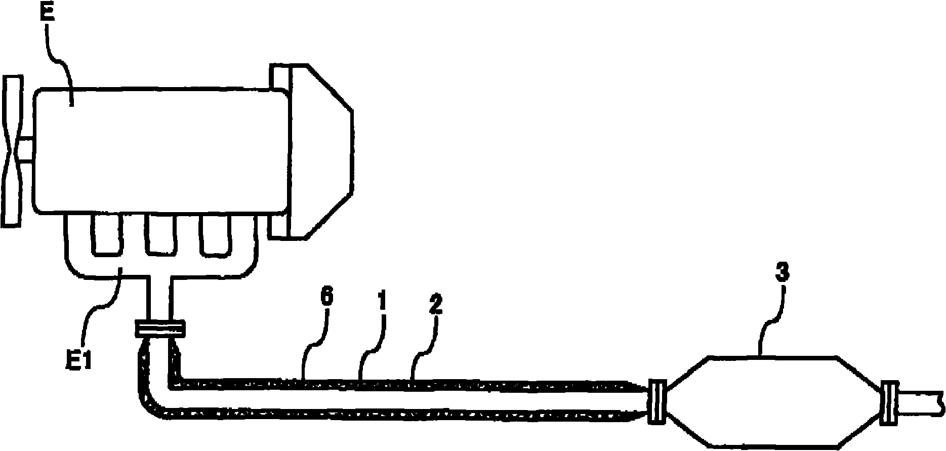
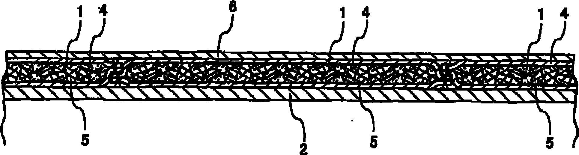
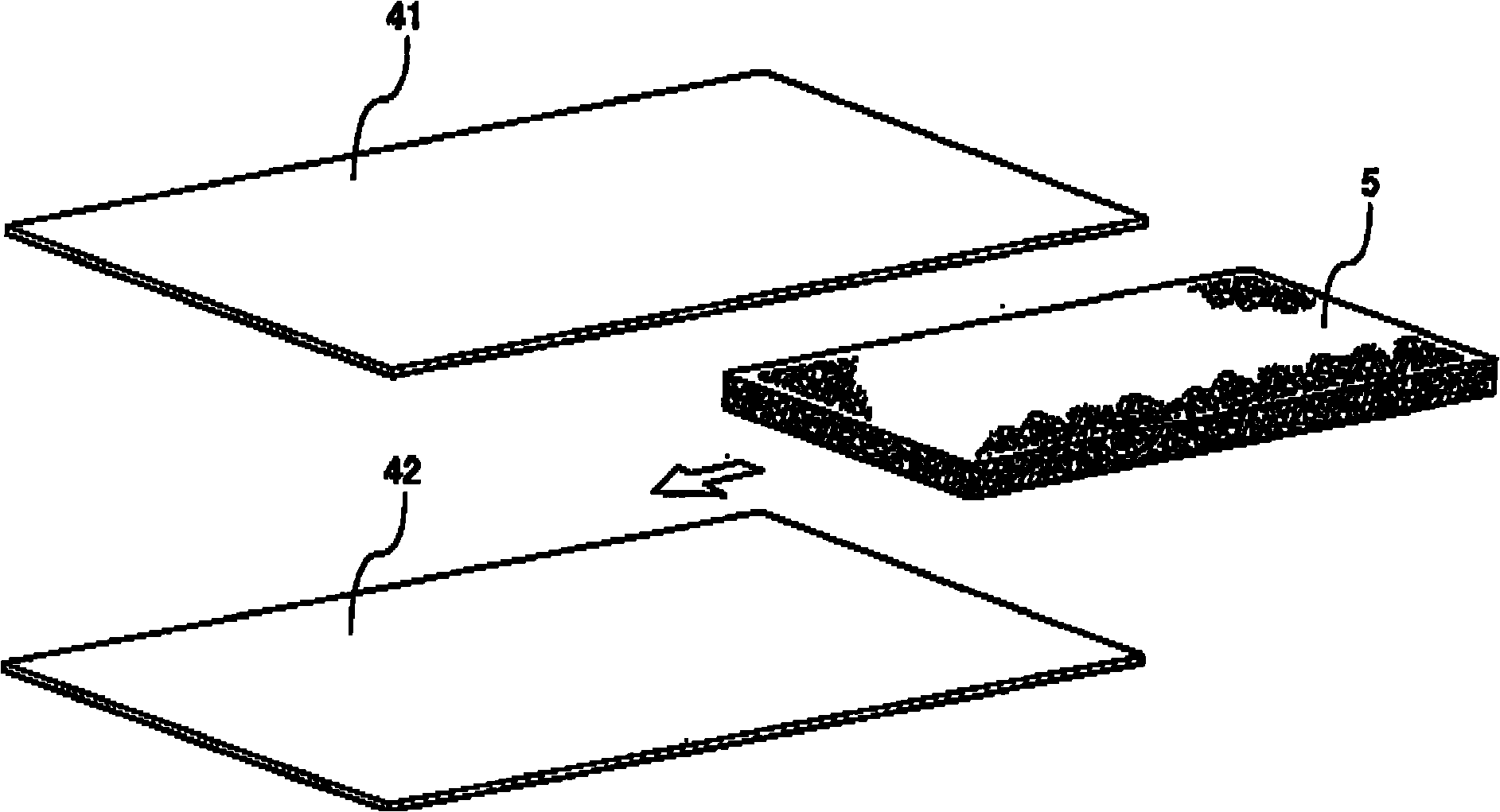
[0019] exist figure 1 Among them, the heat insulating body 1 of the present invention is arranged on the outer periphery of the exhaust pipe 2 from the upstream end of the vehicle exhaust pipe 2 connected to the exhaust manifold E1 of the engine E until it is arranged on the exhaust pipe 2. The inlet side of the catalyst device 3 midway. The enlarged cross-sectional view of the insulation body 1 is in figure 2 Indicated. The thermal insulation body 1 is equipped with a certain length of bag-shaped part 4 along the exhaust pipe 2. Actually, as shown in the figure, the necessary number of thermal insulation bodies 1 are adjacent to each other and wrapped around the outer circumference of the exhaust pipe 2, covering the exhaust manifold E1 The outer periphery of the exhaust pipe 2 between the catalyst device 3 . A deformable plate-shaped thermal insulation material 5 with a thickness of 5 to 15 mm is inserted inside each bag-shaped member 4 , and the inside of the bag-shaped...


PUM

PropertyMeasurementUnit
diameteraaaaaaaaaa
thermal conductivityaaaaaaaaaa

Abstract

The present invention provides a heat insulator for vehicle exhaust pipes, capable of greatly shortening ignition time and having excellent heat insulation. The heat insulator (1) is wound around an outer periphery of a vehicle exhaust pipe (2). The heat insulator comprises a deformable sheet-shaped heat insulating material (5) hermetically encased in a reduced pressure state in a bag member (4) comprised of heat-resistant metal foil.

Description

technical field [0001] The invention relates to a thermal insulation body for a vehicle exhaust pipe and a manufacturing method thereof. Background technique [0002] A catalyst device for purifying exhaust gas is installed in the vehicle exhaust pipe, but the activation temperature of the catalyst is 300°C or higher. Therefore, after the engine is started, it is necessary to rapidly raise the temperature of the catalyst to the above-mentioned temperature, and start rapid exhaust gas purification. In recent years, from the viewpoint of environmental protection, it is necessary to limit the time from the start of the engine to the activation of the catalyst, that is, the light off time (light off time) to an extremely short time, and pursue the pursuit of reducing the temperature of the exhaust gas of the engine. It leads to the catalyst unit and activates the catalyst early. [0003] As one of the measures for preventing the exhaust gas temperature of the engine from dropp...

Claims


Application Information

Patent Timeline
Patent Type & Authority Applications(China)
IPC IPC(8): F01N13/14F01N13/08
CPCF01N13/14F01N13/146F01N2510/02Y10T29/49398
Inventor 中川敬章
Owner NAKAGAWA SANGYO
Why Eureka
Try Eureka