Exhaust gas recirculation system

A recirculation system and exhaust gas technology, applied in the direction of exhaust gas recirculation, charging system, engine components, etc., can solve the problems of insufficient pressure difference between the inlet point and the outlet point, the influence of the work of the compressor, irregular flow, etc.

Inactive Publication Date: 2020-11-06
GUANGZHOU AUTOMOBILE GROUP CO LTD
View PDF8 Cites 1 Cited by
  • Summary
  • Abstract
  • Description
  • Claims
  • Application Information

AI Technical Summary

Problems solved by technology

[0005] 1. The gas introduction point of the exhaust gas recirculation device is downstream of the catalytic converter, where the exhaust gas pressure is low, resulting in insufficient pressure difference between the introduction point and the outlet point of the exhaust gas recirculation device, resulting in a low exhaust gas recirculation rate;
[0006] 2. The exhaust gas and fresh air drawn from the exhaust gas recirculation device are usually sent to the compressor of the supercharger separately. Since the exhaust gas and fresh air are not mixed uniformly in the compressor, the two will flow irregularly, thus affecting the pressure. Negative impact on the work of the turbine

Method used


Image

  • Exhaust gas recirculation system

Examples


Embodiment Construction

[0018] The specific embodiments of the present invention will be described in further detail below with reference to the accompanying drawings and embodiments. The following examples are intended to illustrate the present invention, but not to limit the scope of the present invention.

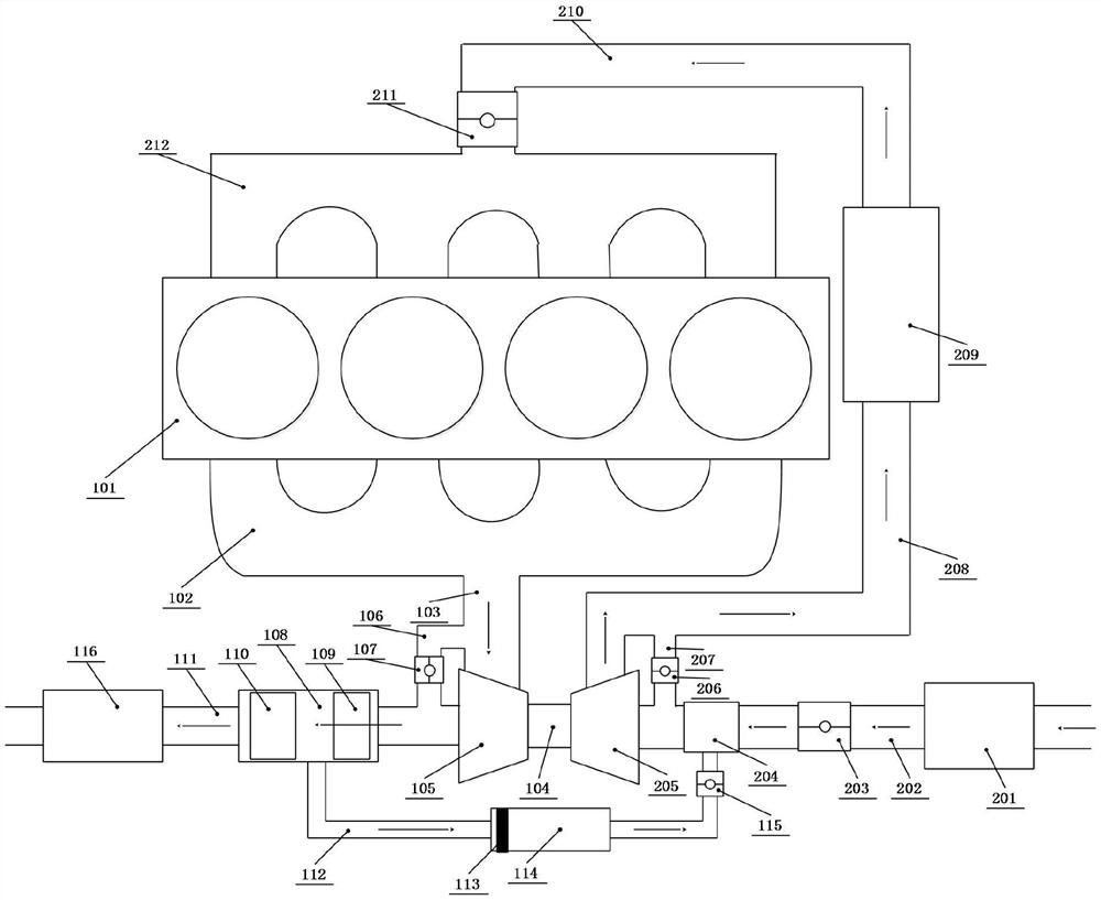
[0019] like figure 1 As shown, the exhaust gas recirculation system of an embodiment of the present invention includes an engine cylinder 101 , an exhaust manifold 102 , a catalyst 108 , a cooler 114 , a supercharger 104 , an air passage 202 and an intake manifold 212 . The supercharger 104 includes a turbine 105 and a pressure turbine 205 .

[0020] The exhaust manifold 102 is merged at the exhaust manifold 103 , and a first branch is connected between the exhaust manifold 103 and the intake end of the turbine 105 , in addition, between the exhaust manifold 103 and the intake end of the catalyst 108 . A second branch, that is, the bypass channel 106, is also connected therebetween. A bypass...


PUM


Abstract

The invention provides an exhaust gas recirculation system. The exhaust gas recirculation system comprises an engine cylinder, an exhaust manifold, a catalyst, a cooler, a supercharger, an air channeland an intake manifold, the supercharger comprises a turbine and a turbine press, the catalyst comprises a first-stage carrier and a second-stage carrier which are separated from each other, the intake end of the catalyst is connected to the turbine, a part, located between the first-stage carrier and the second-stage carrier, of the catalyst is connected to the intake end of the cooler, the airoutlet end of the cooler and the air channel are connected to the intake end of the turbine press, and the air outlet end of the turbine press is connected to the intake manifold through an intake pipeline. Due to the fact that the catalyst comprises the first-stage carrier and the second-stage carrier which are separated from each other, the middle of the first-stage carrier and the middle of thesecond-stage carrier are connected to the intake end of the cooler, an exhaust gas lead-in point of the cooler is located between the first-stage carrier and the second-stage carrier, the exhaust gaspressure at the position is large, and therefore the pressure difference between the lead-in point and the lead-out point of the cooler can be improved, and the exhaust gas recirculation rate is further improved.

Description

technical field [0001] The invention relates to the field of automobiles, in particular to an exhaust gas recirculation system. Background technique [0002] Exhaust gas recirculation (EGR: Exhaust Gas Return) means that part of the exhaust gas discharged from the engine is purified, mixed with fresh air, and sent to the engine cylinder for combustion. The use of exhaust gas recirculation technology in the engine can effectively control the combustion temperature and reduce the emission of NOx. [0003] There are two types of EGR, one is HP (High Pressure) EGR, which directly introduces a part of high temperature and high pressure exhaust gas from the engine exhaust manifold into the exhaust gas recirculation device, and then enters the engine intake manifold; the other is LP (Low Pressure). )EGR is to purify a part of the high temperature and high pressure exhaust gas through the catalytic converter, and then introduce the part of the gas into the exhaust gas recirculation...

Claims


Application Information

Patent Timeline
Patent Type & Authority Applications(China)
IPC IPC(8): F02M26/06F02M26/35F02M26/23F02M26/16F02M26/21
CPCF02M26/06F02M26/16F02M26/21F02M26/23F02M26/35
Inventor 林思聪黄宇李钰怀林承伯
Owner GUANGZHOU AUTOMOBILE GROUP CO LTD
Why Eureka
Try Eureka