
Cutter head mechanism for processing strengthened fin heat-exchange tube and operation method thereof

A technology of heat exchange tubes and cutterheads, which is applied in metal processing equipment, routers, manufacturing tools, etc., can solve the problems of inability to guarantee the mass production and quality of heat exchangers, insufficient strength of the root of warp blades, and easy fall off of warp blades, etc. problem, to achieve the effect of simple structure, low production cost and simple manufacture

Active Publication Date: 2012-07-25
GUANGDONG IND TECHN COLLEGE
View PDF0 Cites 0 Cited by
  • Summary
  • Abstract
  • Description
  • Claims
  • Application Information

AI Technical Summary

Problems solved by technology

Although this kind of planing processing can also complete the processing of warped fin heat exchange tubes, the processing time is too long, and the thickness of warped fins is uniform, the root strength of warped fins is insufficient, and warped fins are easy to fall off, which cannot guarantee the production of heat exchangers. Manufacturers demand for mass production and quality

Method used


Image

  • Cutter head mechanism for processing strengthened fin heat-exchange tube and operation method thereof
  • Cutter head mechanism for processing strengthened fin heat-exchange tube and operation method thereof
  • Cutter head mechanism for processing strengthened fin heat-exchange tube and operation method thereof

Examples


Embodiment 1

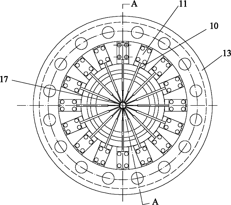
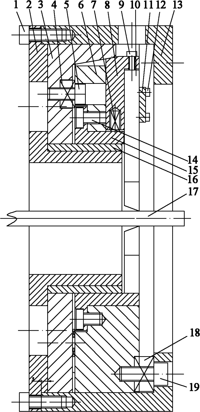
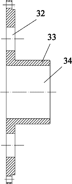
[0038] Figure 1 to Figure 10 Shows the specific structural diagram of this embodiment, such as figure 2 As shown, the enhanced blade heat exchange tube processing cutter head mechanism includes an end cover 2, a push plate mechanism, a cutter head 6, sixteen sliders 8, a shaft sleeve 16, a support sleeve 15 and a cutter head jacket 13. Cover 2 is fixedly connected with cutterhead outer cover 13, as image 3 As shown, the inner circumference of the end cover 2 is a boss 33, and the shaft sleeve 16 cooperates with the outer circumference of the boss 33; cavity; the push plate mechanism, cutter head 6, and sixteen sliders 8 are sequentially placed in the cavity, and the push plate mechanism is connected with cutter head 6 and sixteen slide blocks 8 respectively; the push plate mechanism Cooperate and connect with the inner wall of the end cover 2; the inner circumference of the push plate mechanism and the support sleeve 15 are all matched with the outer circumference of the ...

Embodiment 2

[0056] This embodiment has the same structure as Embodiment 1 except the following features: the gap between the outer end surface of the cutter head and the inner end face of the cutter head groove is 2mm.

[0057] The slope of the side wall of the cutter head groove is 30 degrees; the diameter of the primary hole of the stepped hole on the push plate is 10 mm larger than the diameter of the secondary hole.

[0058] The size of the gap between the inner end surface of the cutter head casing and the end surface of the protrusion is 0.35mm.

[0059] The diameter of the primary hole of the stepped hole of the cutterhead is 10 mm larger than the diameter of the secondary hole.

[0060] The axle sleeve is a cast iron sleeve.

[0061] The number of the bumps, the number of slide block grooves, the number of planers, the number of slide blocks, the number of push plate springs, the number of bolts of the push plate mechanism, and the number of holes of the cutter head Twenty respe...

Embodiment 3

[0063] The structure of this embodiment is the same as that of Embodiment 1 except the following features: the gap between the outer end surface of the cutter head and the inner end face of the cutter head slot is 1.5mm.

[0064] The inclination of the side wall surface of the cutter head groove is 15 degrees; the diameter of the primary hole of the stepped hole on the push plate is 8 mm larger than that of the secondary hole.

[0065] The size of the gap between the inner end surface of the cutter head casing and the end surface of the protrusion is 0.25mm.

[0066] The diameter of the primary hole of the stepped hole of the cutter head is 8 mm larger than the diameter of the secondary hole.

[0067] The number of the bumps, the number of slide block grooves, the number of planers, the number of slide blocks, the number of push plate springs, the number of bolts of the push plate mechanism, and the number of holes of the cutter head Fifteen respectively.


PUM


Abstract

The invention provides a cutter head mechanism for processing a strengthened fin heat-exchange tube and an operation method thereof, wherein the cutter head mechanism comprises an end cover, a pushing disc mechanism, a cutter head, a plurality of sliders, a shaft sleeve, a supporting sleeve and a cutter head coat, wherein the end cover is fixedly connected to the cutter head coat; the inner circumference of the end cover is a boss; the shaft sleeve is fitted with the outer circumference of the boss; the pushing disc mechanism is respectively connected to the inner wall of the end cover, the cutter head and the plurality of sliders; the pushing disc mechanism and the supporting sleeve are in fitting sleeve joint with the shaft sleeve; the cutter head is provided with an inner hole which isfitted with the outer circumference of the supporting sleeve; the plurality of sliders are connected to the outer circumference of the supporting sleeve; a plurality of lugs are arranged on the cutter head, each lug is connected to the cutter head coat; a slider slot is formed between every two adjacent lugs; the plurality of sliders are respectively arranged in each slider slot; each slider is provided with a groove; and the end cover and the cutter head coat are provided with inner holes with superposed centre lines. In the invention, a plurality of plane cutters can be installed for continuously process, so as to realize efficient production.

Description

technical field [0001] The invention belongs to the technical field of mechanical manufacturing, and in particular relates to a mechanism for strengthening the processing cutterhead of warp fin heat exchange tubes and an operation method thereof. Background technique [0002] Warped fin heat exchange tubes have been widely used in the field of heat exchangers in recent years. Because they can increase the heat dissipation area of ​​heat exchange tubes, and the heat transfer tube body is formed by planing, the heat transfer effect is good, but due to Processing difficulties have been unable to meet the needs of industrial production. The main difficulty in processing is that there has not been an efficient processing cutter head. The current processing method is to plan out one warp at a time. How many warps are there on the circumference and length of the heat exchange tube, it needs to be planed as many times as possible. Although this kind of planing processing can also c...

Claims


Application Information

Patent Timeline
Patent Type & Authority Patents(China)
IPC IPC(8): B23D13/00
Inventor 康俊远王军赵战峰陈良特钟海生
Owner GUANGDONG IND TECHN COLLEGE
Learn More