Tool head positioning structure of head shaking wrench

A technology of positioning structure and tool head, which is applied in the field of oscillating wrench, can solve the problems of inaccurate positioning, limited stability, displacement of the control rod 71, etc., and achieve accurate and stable positioning or swing, high holding stability, and improved stability degree of effect

Active Publication Date: 2012-09-05
INFAR IND CO LTD
View PDF0 Cites 0 Cited by
  • Summary
  • Abstract
  • Description
  • Claims
  • Application Information

AI Technical Summary

Problems solved by technology

[0004] 1. The stability is limited: since the top block 72 stops on the inclined surface 710, when receiving a slightly larger pushback force, following the guiding direction of the inclined surface 710, the control rod 71 will produce an unnecessary Backlash force, so that the state of the elastic clamping of the control rod 71 cannot be effectively maintained, that is, the control rod 71 will have a component force of displacement, and has the disadvantage of improper movement, making it difficult to maintain the control rod 71 On the position of pushing away this jack block 72 and positioning this tool head 90 angles, so there is a need for improvement
[0005] 2. Finger pressing does not meet the convenience requirements of use: since the protruding direction of the control rod 71 is on the side of the overall wrench in the horizontal direction, the user must press sideways to control whether the tool head 90 is positioned or not. It is a new way of use, and it is difficult to confirm whether the pressing is confirmed or not, so there is a need for improvement
[0006] It can be seen that the current common shaking head wrench may not be able to locate, or the positioning is not accurate, or there must be other operating methods for positioning.

Method used


Image

  • Tool head positioning structure of head shaking wrench
  • Tool head positioning structure of head shaking wrench
  • Tool head positioning structure of head shaking wrench

Examples


Embodiment Construction

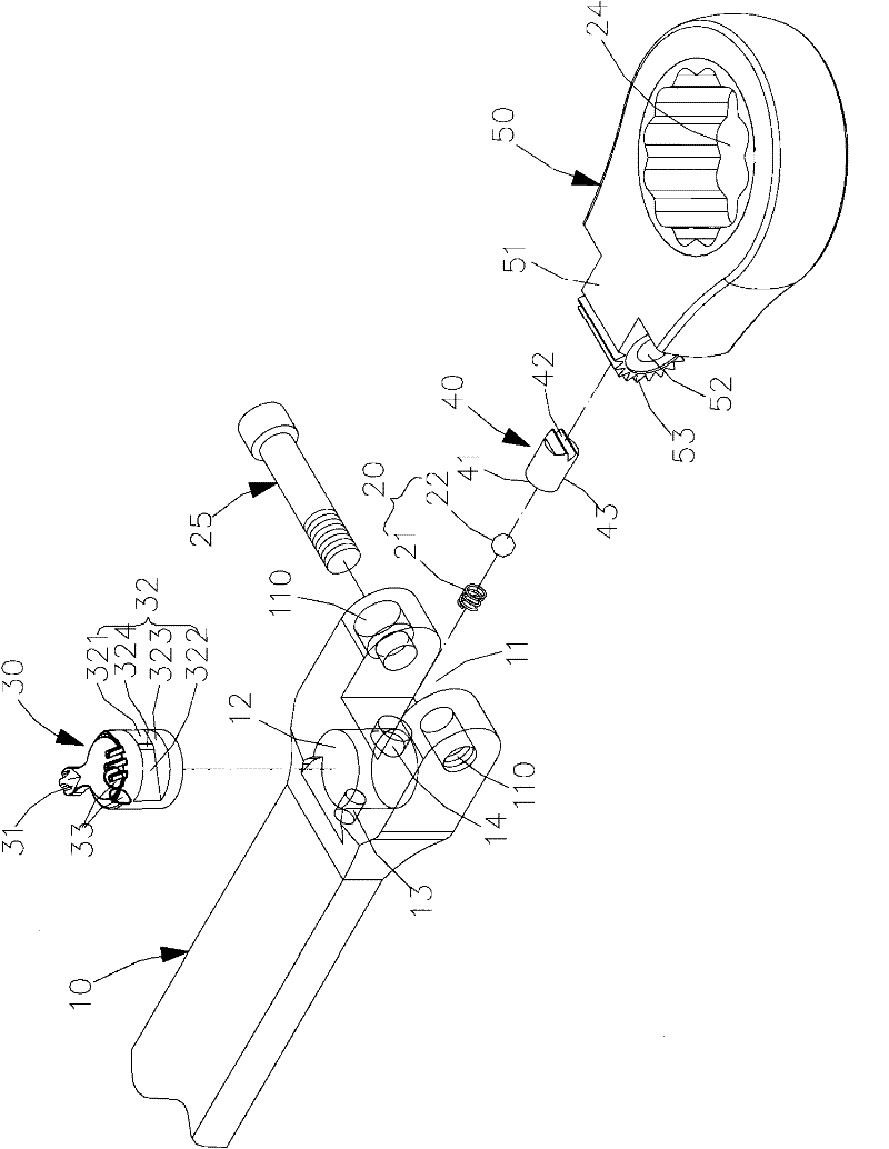
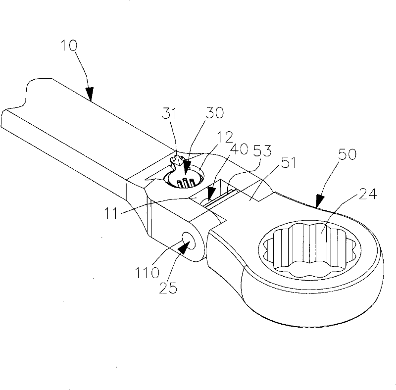
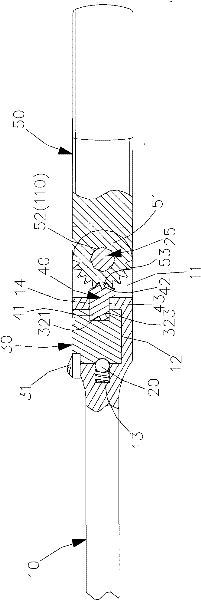
[0026] An embodiment of the tool head positioning structure of the shaking head wrench of the present invention is as follows: figure 1 , figure 2 , image 3 shown, including:

[0027] One end of a handle 10 is pivotally provided with a tool head 50, and the tool head 50 is provided with a convex fitting portion 51 at the pivot point. Along the same circle center as the pivot hole 52, an engaging portion 53 with a plurality of tooth shapes is provided, and a tool portion 24 is additionally provided on the tool head 50, and the tool portion 24 is a matching screw, nut or tool head;

[0028] The handle 10 is provided with a concave pivot joint 11 at the pivot joint between one end and the tool head 50 for the fitting part 51 of the tool head 50 to be inserted into. The two side walls of the pivot joint 11 are provided with horizontal The through pivot hole 110 is aligned with the pivot hole 52 of the matching portion 51 to cooperate with a shaft bolt 25 to pass through and ...


PUM


Abstract

The invention discloses a tool head positioning structure of a head shaking wrench. A clamping part which is close to or far away from a tool head under the control of rotation of a control part is arranged between a wrench handle and the tool head; the control part keeps at position after a user wrenches the tool head by two continuous faces with different depths on the control part, namely a pushing part and a retreating part, and an elastic positioning group positioning the control part; and the pushing part or the retreating part on the control part is opposite to the clamping part, so that the clamping part contacts and positions the tool head relative to an end part of the tool head or can swing without contacting the tool head, and the tool head can be positioned quickly and stably.

Description

technical field [0001] The invention relates to an oscillating wrench, in particular to a tool head positioning structure of an oscillating wrench. Background technique [0002] The current shaking head wrench is suitable for pivotally installing a tool head in a swinging shape at the end of the handle body of the tool, commonly known as a shaking head. The most traditional form is a simple pivoting combination between the handle and the tool head. There is no structure to fix the positioning of the tool head, so when the wrench is used, the tool head cannot be positioned accurately, and when the workpiece is pulled, the tool head in the form of free swinging head will have the disadvantage of improper swing, so there is a need for improvement Therefore, some operators have additionally provided a tooth-shaped structure at the outer periphery of the pivot joint of the tool head, and provided an elastic clamping structure for pushing the steel ball with an elastic member at a...

Claims


Application Information

Patent Timeline
Patent Type & Authority Patents(China)
IPC IPC(8): B25B23/00
Inventor 陈泰宏
Owner INFAR IND CO LTD
Why Eureka
Try Eureka