
Feet-type robot

A robot and foot-type technology, applied in the field of robots, to achieve the effect of good coordination, simple structure and convenient maintenance

Active Publication Date: 2015-12-02
GUANGXI UNIV
View PDF5 Cites 7 Cited by
  • Summary
  • Abstract
  • Description
  • Claims
  • Application Information

AI Technical Summary

Problems solved by technology

[0004] The object of the present invention is to provide a foot-legged robot, thereby overcoming the shortcoming that the existing foot-footed robot needs to be moved under complex mechanism control

Method used


Image

  • Feet-type robot
  • Feet-type robot
  • Feet-type robot

Examples


Embodiment 1

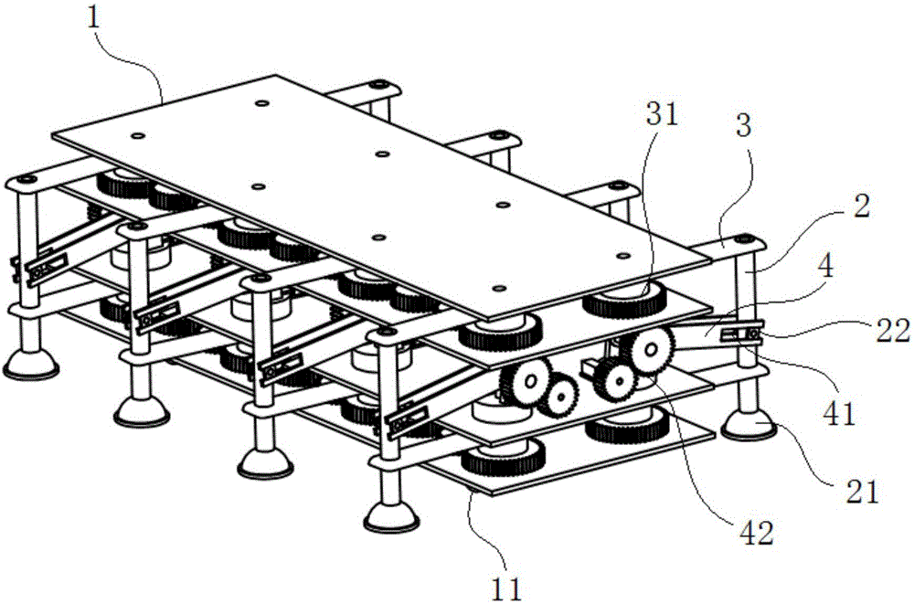
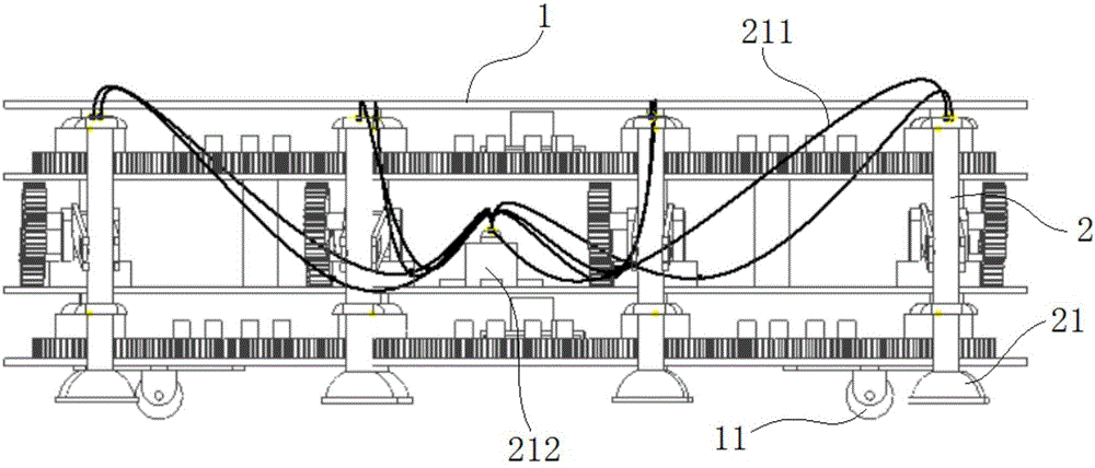
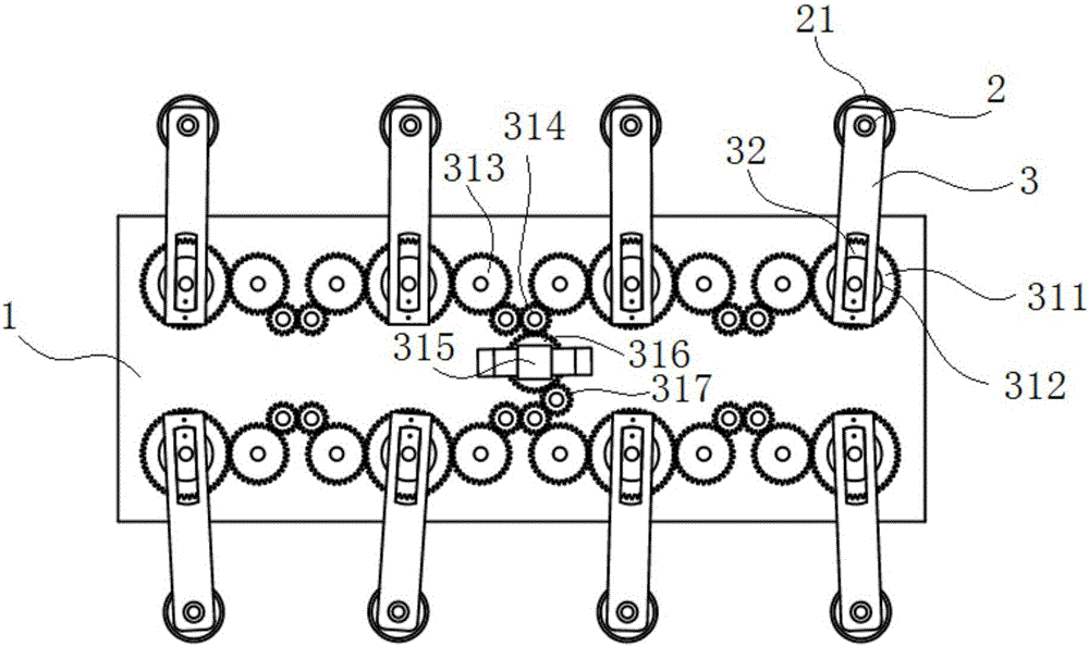
[0025] Such as Figure 1 to Figure 4 As shown, the first embodiment according to the specific embodiment of the present invention is: a foot-type robot, which includes a fuselage 1, a foot 2, a translation swing bar 3 and a foot lift swing bar 4, wherein:

[0026] Such as figure 1 and figure 2 As shown, the bottom of the fuselage 1 is provided with wheels 11 , and the fuselage 1 is supported and moved by the wheels 11 . The foot 2 is in the shape of a hollow rod, the lower end of the foot 2 is provided with a vacuum suction cup 21 , and the upper end of the foot 2 is connected to an air pump 212 through a hose 211 , and the air pump 212 is arranged on the body 1 . Four pairs of feet 2 are sequentially arranged on the fuselage 1 from front to back, and eight feet 2 are arranged on the fuselage 1, and two feet 2 of each pair of feet 2 are symmetrically arranged on the fuselage respectively. 1 on the left and right sides. When the air pump 212 pumps air through the foot 2 to...

Embodiment 2

[0043] On the basis of Example 1, further, as figure 1 As shown, the slider 22 is arranged in the middle of the foot 2, so that the foot lifting swing rod 4 is connected to the middle of the foot 2; and the upper and lower parts of the foot 2 are respectively sleeved on the outer ends of the two translation swing rods 3 ; The front and rear swing mechanism 31 of the upper translation swing rod 3 and the front and rear swing mechanism 31 of the lower translation swing rod 3 are respectively powered by two first power mechanisms. The fuselage 1 is respectively provided with three layers of pallets, the upper and lower two layers of pallets are respectively used to set the upper and lower layers of the front and rear swing mechanism 31 and the first power mechanism, and the middle pallet is used to set the up and down swing mechanism and the second power mechanism . And the upper end of the fuselage 1 is provided with a cover plate for protecting the fuselage 1 and installing th...


PUM


Abstract

The invention discloses a feet-type robot. The feet-type robot comprises a robot body, feet, translation swinging rods, a first power mechanism, a foot lifting swinging rods and a second power mechanism, wherein wheels are arranged at the bottom of the robot body; the feet are shaped like hollow rods; vacuum suckers are arranged at the lower ends of the feet; the upper ends of the feet are connected with an air pump through hoses; the four pairs of feet are arranged on the robot body in sequence from front to back; each foot movably sleeves the outer end of each translation swinging rod; each translation swinging rod is arranged on the robot body through a front-and-back swinging mechanism; the first power mechanism is used for providing power to the front-and-back swinging mechanism; a first sliding slot is formed in the outer end of each foot lifting swinging rod; a sliding block is arranged on each foot; The feet are movably embedded in the first sliding slots of the foot lifting swinging rods through the sliding blocks; each foot lifting swinging rod is arranged on the robot body through a up-and-down swinging mechanism; and the second power mechanism is used for providing power to the up-and-down swinging mechanisms. According to the feet-type robot disclosed by the invention, it is easy to drive the feet to do translation and foot lifting actions so that the robot is conveniently controlled to move.

Description

technical field [0001] The invention relates to the field of robots, in particular to a legged robot. Background technique [0002] With the continuous development of robot technology, the application fields of walking robots are becoming wider and wider. Robots can replace humans to complete high-intensity, difficult, and dangerous tasks, or perform home care work. At present, in the motion mechanism of mobile robots, wheeled, crawler and foot-foot mechanisms are commonly used. Compared with wheeled robots or crawler robots, foot-footed robots have higher mobility and good performance. adaptability. At present, most of the foot-legged robots adopt the scheme of setting multiple joints on each foot, and each joint is controlled by a motor, which not only makes the structure of the robot more complicated, but also increases the complexity of the control. Therefore, the existing foot-footed robots need to move under the control of complex mechanisms. [0003] The informati...

Claims


Application Information

Patent Timeline
Patent Type & Authority Applications(China)
IPC IPC(8): B62D57/024
Inventor 周晓蓉王一羽徐敏刘应军阎凌云黄宏星陈定堃
Owner GUANGXI UNIV
Learn More