Misfueling preventing apparatus

a technology of misfueling and preventing apparatus, which is applied in the direction of vehicle components, propulsion parts, transportation and packaging, etc., can solve the problems of reducing the mechanical strength, limiting the hardness of the annular ring, and known misfueling preventing apparatuses adapting the annular member, etc., to facilitate the elastic deformation of the flapper, reduce the car manufacturing cost, and facilitate the effect of handling and installation

Active Publication Date: 2016-11-29
ASTEER
View PDF13 Cites 7 Cited by
  • Summary
  • Abstract
  • Description
  • Claims
  • Application Information

AI Technical Summary

Benefits of technology

[0006]In order to elastically deform the annular ring made of plastic, there is a limitation on a hardness of the annular ring. This limitation results in lowering in a mechanical strength and lowering in a durability of the annular ring. The annular ring is repeatedly enlarged by a nozzle. This results in a relaxation of stress of the annular ring with age. If the relaxation of stress progresses, the annular ring does not revert to an original shape and is left enlarged. This impairs a function of discriminating type of nozzle since a nozzle can open the flapper without contacting the annular ring.
[0008]This disclosure provides a misfueling preventing apparatus which can discriminate outer diameter of the nozzle, which is inserted into a fuel filler pipe, without adapting the annular ring made of plastic elastically deformed by being pressed with the nozzle.
[0010]It is preferable that each of the first trigger projection and the second trigger projection has an inclining face or an inclining edge on its upper side. The inclining face or the inclining edge descends to projecting direction of each of the first trigger projection or the second trigger projection. When inserting the diesel nozzle, the inclining face or the inclining edge slidably moves outside along the tip of diesel nozzle by being pressed down with the diesel nozzle to smoothly swing the first link arm and the second link arm to the opening direction.
[0013]The flapper may be configured by a plate having at least one concaved groove on or next to the stopper projection. Flapper may be configured by a plate having at least one pair of slits along an extending direction of the stopper projection. The concaved groove or slit facilitates the flapper to elastically deform when too much load is applied on the flapper, and prevents the flapper from being destroyed with too much load.
[0014]It is preferable that the apparatus further include an upper housing coupled to the base. The first link arm and the second link arm are supported by a plurality of supporting projections provided on the base and a plurality of supporting projections provided on the upper housing to swing. By coupling the upper housing and the base, misfueling preventing apparatus is modularized. Modularized apparatus is easy to handle and install. Plurality of supporting projections of the upper housing and the base prevents the first link arm and the second link arm from being detached when they swing.
[0015]Misfueling preventing apparatus may further include a spacer. The spacer is externally fitted to the base. Inner diameter of a fuel filler pipe sometimes varies depending on a type of vehicle. By exchanging the spacer depending the type of vehicle, a misfueling preventing apparatus having the same specification can be installed. This facilitates to reduce a car manufacturing cost.

Problems solved by technology

However, known misfueling preventing apparatuses adapting the annular member as explained above has following defects.
In order to elastically deform the annular ring made of plastic, there is a limitation on a hardness of the annular ring.
This limitation results in lowering in a mechanical strength and lowering in a durability of the annular ring.
This results in a relaxation of stress of the annular ring with age.
This impairs a function of discriminating type of nozzle since a nozzle can open the flapper without contacting the annular ring.
The annular ring elastically deformed with a nozzle causes too much friction resistance when inserting the nozzle.
Therefore, a portion slidably contacting to the nozzle becomes long too, and generates large friction resistance between the nozzle.
This friction resistance is not overlooked when inserting the nozzle into the fuel filler port since it impairs an operational feeling of the nozzle when refueling.

Method used


Image

  • Misfueling preventing apparatus
  • Misfueling preventing apparatus
  • Misfueling preventing apparatus

Examples


Embodiment Construction

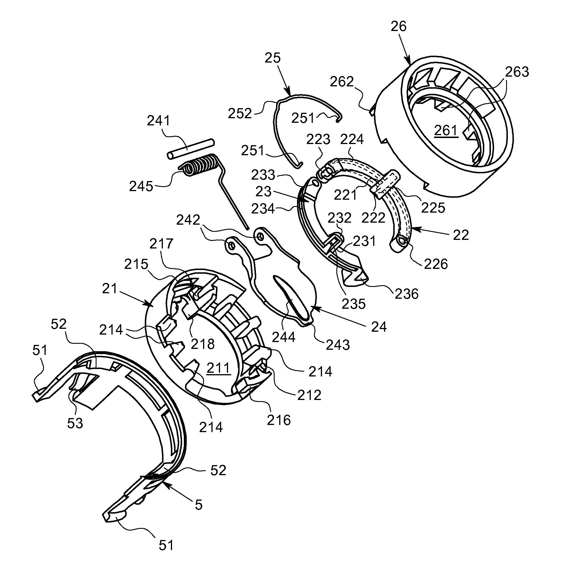
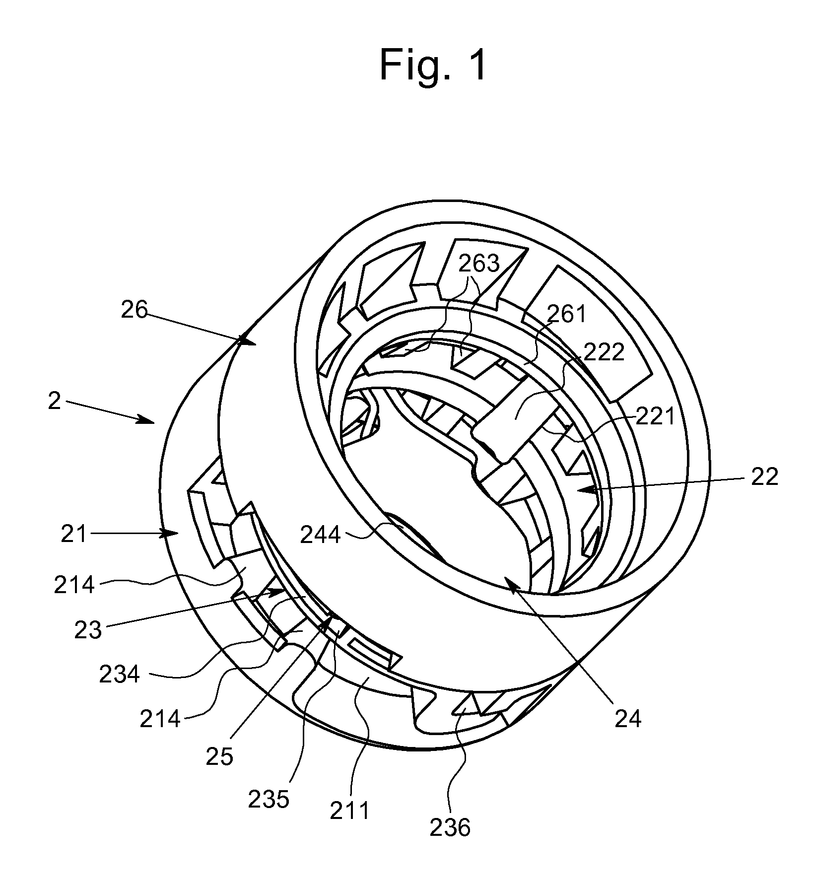
[0037]Embodiments of the present disclosure is explained with reference to Figs. For a convenience of explanation, a direction to which a fuel filler nozzle 3 or 4 is inserted is referred to as “lower side”. The opposite direction to the lower side is referred to as “upper side”. Direction to which a first link arm 22 is located in a plain view, such as FIGS. 5, 8, 9, 14, 16, 18, 20, is referred to as “right side”. Direction to which a second link arm 23 is located in a plain view of a misfueling preventing apparatus 2, such as FIGS. 5, 8, 9, 14, 16, 18, 20, is referred to as “left side”. FIGS. 1 to 6 and FIGS. 10 to 21 illustrate an embodiment of the present disclosure. FIG. 7 illustrates another embodiment of the present disclosure. FIG. 8 illustrates still another embodiment of the present disclosure. FIG. 9 illustrates still another embodiment of the present disclosure.

[0038]The embodiment illustrated in FIGS. 1 to 6 and FIGS. 10 to 21 is explained in the following. A misfueling...


PUM


Abstract

A misfueling preventing apparatus discriminates a fuel filler nozzle based on an outer diameter of the fuel filler nozzle. The misfueling preventing apparatus includes a base, a first link arm, a second link arm, a flapper and a stopper. The first link arm has a first trigger projection. The second link arm has a second trigger projection. If the fuel filler nozzle of light diesel oil pushes the first trigger projection and the second trigger projection, the first link arm and second link arm swing to a direction to which the first link arm and second link arm open to, placing the flapper in an openable state.

Description

BACKGROUND OF THE INVENTION[0001]1. Field of the Invention[0002]The present disclosure relates to a misfueling preventing apparatus, which discriminates between a fuel filler nozzle for gasoline and a fuel filler nozzle for light diesel oil based on an outer diameter of a fuel filler nozzle to be inserted to a fuel filler port.[0003]2. Description of the Related Art[0004]An outer diameter of a fuel filler nozzle for fueling a light diesel oil (hereinafter sometimes referred to as “diesel nozzle”) is larger than outer diameter of a fuel filler nozzle for fueling gasoline (hereinafter, referred to as gasoline nozzle). Apparatuses preventing an operator from misfueling (hereinafter, sometimes referred to as “misfueling preventing apparatus”) which discriminate between the diesel nozzle and the gasoline nozzle are known. For example, the inventions disclosed in US 2012 / 0024422 A1, US 2011 / 0139779 A1, and WO 2010 / 113063 A1. These apparatuses discriminate a type of nozzle based on a diffe...

Claims


Application Information

Patent Timeline
Patent Type & Authority Patents(United States)
IPC IPC(8): B60K15/07B60K15/077B60K15/04
CPCB60K15/077B60K15/04B60K2015/0461B60K2015/0483
Inventor YOSHIDA, HIROMITSUONO, TAKAMI
Owner ASTEER
Why Eureka
Try Eureka