Cell-module cartridge and mid-large battery module including the same

a battery module and cartridge technology, applied in the field of cell module cartridges, can solve the problems of low manufacturing cost of pouch-shaped batteries, large external impact and vibration, and the electrical connection between the electrode terminals necessary for constructing the battery module, etc., and achieve the effects of high output, limited installation space, and large capacity

Active Publication Date: 2010-06-03
LG ENERGY SOLUTION LTD
View PDF6 Cites 56 Cited by
  • Summary
  • Abstract
  • Description
  • Claims
  • Application Information

AI Technical Summary

Benefits of technology

[0050]The battery modules may be electrically connected to each other in various structures depending upon a desired capacity and output, and therefore, the battery module assembly is applicable to various devices. Consequently, the middle- or large-sized battery module and the battery module assembly according to the present invention are preferably used as a power source for electric

Problems solved by technology

Furthermore, devices, which are subject to a large number of external impacts and vibrations, such as electric bicycles and electric vehicles, require stable electrical connection and physical coupling between components constituting the battery module.
Especially, much interest is currently generated in the pouch-shaped battery, including a sheathing member made of an aluminum laminate sheet, because the weight of the pouch-shaped battery is small, and the manufacturing costs of the pouch-shaped battery are low.
First, the pouch-shaped battery is constructed in a structure in which the plate-shaped electrode terminals protrude from the upper end of a battery case, with the result that the electrical connection between the electrode terminals necessary for constructing a battery module is difficult. The electrical connection between the electrode terminals is accomplished generally by coupling the electrode terminals to each other by welding using wires, plates, or bus bars; however, the coupling between the plate-shaped electrode terminals by welding is not easy. Generally, the plate-shaped electrode terminals are partially bent, and the metal plates or the bus bars are welded to the bent portions of the plate-shaped electrode terminals, which requires skilled technique and complicates a process for electrically connecting the electrode terminals to each other. Furthermore, the coupled region may be separated from each other due to external impact, which causes the defect of the pouch-shaped battery.
Second

Method used


Image

  • Cell-module cartridge and mid-large battery module including the same
  • Cell-module cartridge and mid-large battery module including the same
  • Cell-module cartridge and mid-large battery module including the same

Examples


Embodiment Construction

[0061]Now, preferred embodiments of the present invention will be described in detail with reference to the accompanying drawings. It should be noted, however, that the scope of the present invention is not limited by the illustrated embodiments.

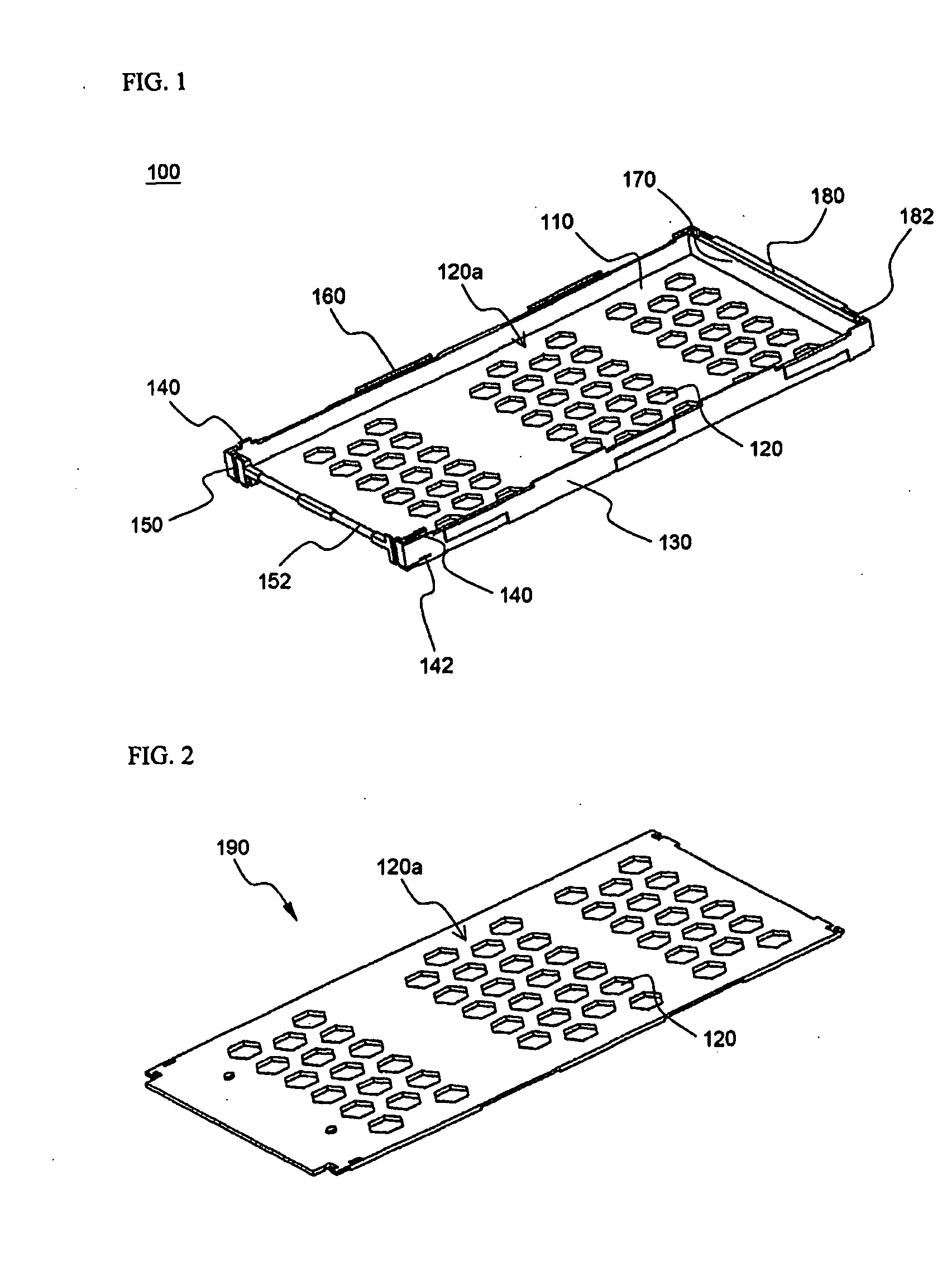
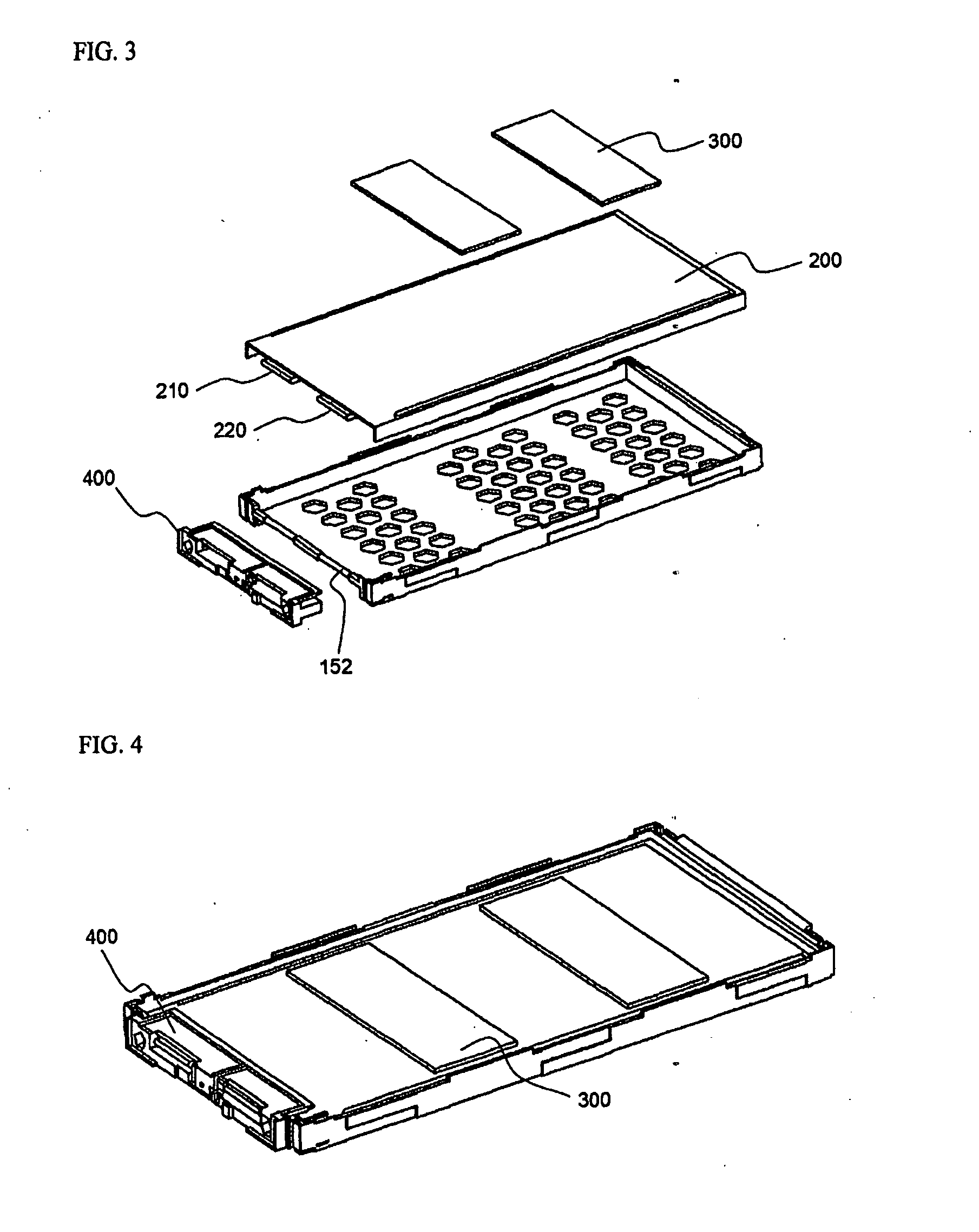
[0062]FIGS. 1 and 2 are perspective views respectively illustrating a cartridge body and a top cover constituting a cell module cartridge according to a preferred embodiment of the present invention, and FIGS. 3 and 4 are typical views illustrating a process for mounting a battery cell to the cell module cartridge of FIG. 1.

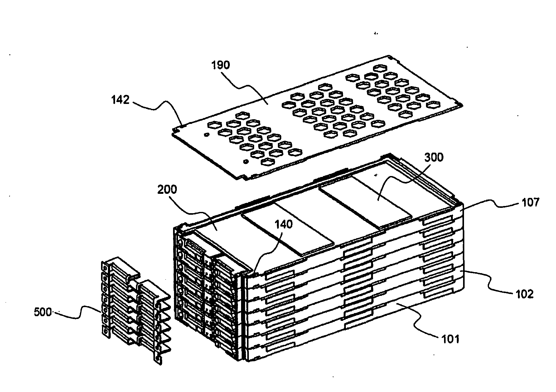
[0063]Referring to these drawings, the cartridge body 100 is constructed in a rectangular structure corresponding to a plate-shaped battery cell 200 (hereinafter, will be shortly referred to as a “battery cell”) such that the battery cell 200 is mounted to the cartridge body 100. The cartridge body 100 is open at the top thereof. Also, the cartridge body 100 is provided at the bottom 110 thereof with a plurality of throug...


PUM


Abstract

Disclosed herein are a cell module cartridge including a cartridge body constructed in a rectangular structure in which a plate-shaped secondary battery cell is mounted to the cartridge body, the cartridge body being open at the top thereof, and a top cover mounted to the open top of the cartridge body while the battery cell is mounted to the cartridge body, wherein the cartridge body is provided at the bottom thereof with a plurality of through-holes, the cartridge body is provided at one side of the upper and lower ends of each side wall thereof with a coupling protrusion and a coupling groove, and the cartridge body is provided at the front thereof with a coupling part, to which an additional member for mounting an electrode terminal connecting member is coupled in an assembly fashion, such that the electrode terminal connecting member is stably connected to the corresponding electrode terminal of the corresponding battery cell, and a middle- or large-sized battery module including the same.

Description

FIELD OF THE INVENTION[0001]The present invention relates to a cell module cartridge used for manufacturing a middle- or large-sized battery module and a middle- or large-sized battery module including the same, and, more particularly, to a cell module cartridge including a cartridge body constructed in a rectangular structure corresponding to a plate-shaped secondary battery cell such that the battery cell is mounted to the cartridge body, the cartridge body being open at the top thereof, and a top cover mounted to the open top of the cartridge body while the battery cell is mounted to the cartridge body, wherein the cartridge body is provided at the bottom thereof with a plurality of through-holes, the cartridge body is provided at one side of the upper and lower ends of each side wall thereof with a coupling protrusion and a coupling groove, and the cartridge body is provided at the front thereof with a coupling part, to which an additional member for mounting an electrode termin...

Claims


Application Information

Patent Timeline
IPC IPC(8): H01M2/02H01M50/528H01M50/202H01M50/211H01M50/296H01M50/503H01M50/51H01M50/512H01M50/569
CPCH01M2/1077H01M2/206H01M10/052Y02T10/7011H01M10/5032H01M10/5055H01M10/5059H01M10/5004H01M10/647H01M10/6557H01M10/6555H01M10/613Y02E60/10H01M50/296H01M50/512H01M50/51H01M50/202H01M50/503H01M50/569H01M50/211
Inventor SHIN, YONGSHIKKIM, JEEHOHA, JIN WOONG
Owner LG ENERGY SOLUTION LTD
Why Eureka
Try Eureka