
Supporting frame for pellicle, pellicle, method for manufacturing same, exposure master using same, and method for manufacturing semiconductor device

a technology of supporting frame and pellicle, which is applied in the direction of microlithography exposure apparatus, photomechanical treatment, instruments, etc., can solve the problems of reducing the time required to reach the vacuum, affecting the effect of pellicle degradation, and difficult air to pass through the filter. , to achieve the effect of suppressing the degradation of the filter and less time to be evacuated

Active Publication Date: 2021-01-14
MITSUI CHEM INC
View PDF0 Cites 0 Cited by
  • Summary
  • Abstract
  • Description
  • Claims
  • Application Information

AI Technical Summary

Benefits of technology

The patent describes a problem that occurs when a vacuum is applied to a photomask and a pellicle, which can cause the pellicle film to sag or bulge. To prevent damage to the pellicle film, a vent hole is needed. However, limited installation space makes it challenging to adequately ventilate through the vent hole while preventing foreign matter from entering the pellicle. The manufacturing process described in the patent takes less time to be evacuated and helps suppress degradation of the filter.

Problems solved by technology

If area of the filter on the support unit of the pellicle is small when evacuating the inside of a lithographic device using an EUV pellicle, the air is difficult to pass through the filter, and it takes relatively long time to create a vacuum inside the pellicle.
In particular, since the height of the support unit itself is low, the filter area is limited to in the type of providing a hole in side surface direction of the support unit as described in International Patent Publication No. 2016 / 043292 described in the prior art, therefore, it was found that there is a problem for further shortening the time required to reach the vacuum.
Further, since the filter is exposed to an exposure surface in the type of providing the hole of longitudinal direction of the support unit as in International Patent Publication No. 2016 / 043301 described in the prior art, therefore, it was found that there is a problem in which the EUV light hits the filter and the degradation of the filter progresses relatively quickly.
Furthermore, in International Patent Publication No. 2016 / 043301 which is a prior art, drilling is required in the Si wafer which is a starting substrate of the pellicle film for an EUV such as SiN, p-Si, SiC, it was found that the fabrication process is relatively complicated and expensive.
On the other hand, embedding the filter inside the frame body further reduces the filter degradation.
On the other hand, embedding filter inside the frame body further reduces the filter degradation.
On the other hand, embedding the filter inside the frame body further reduces the filter degradation.

Method used


Image

  • Supporting frame for pellicle, pellicle, method for manufacturing same, exposure master using same, and method for manufacturing semiconductor device
  • Supporting frame for pellicle, pellicle, method for manufacturing same, exposure master using same, and method for manufacturing semiconductor device
  • Supporting frame for pellicle, pellicle, method for manufacturing same, exposure master using same, and method for manufacturing semiconductor device

Examples


embodiment 1

Modification of Embodiment 1

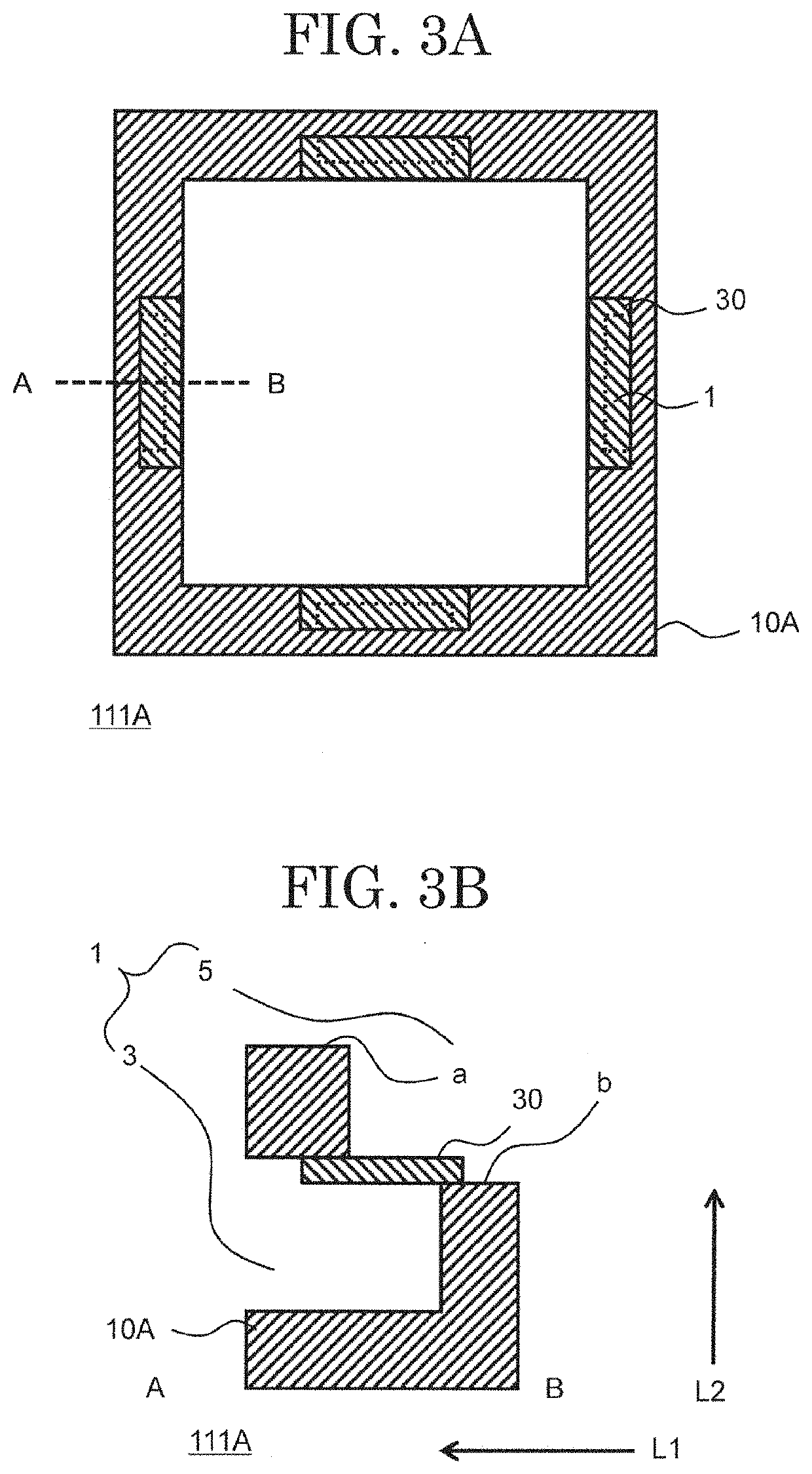
[0125]In Embodiment 1, the support frame 111B is exemplified by using the frame body in which the hole 3 extending in the first direction L1 is the inner edge vent of the frame body and the hole 5 extending in the second direction L2 intersecting with the first direction L1 is the outer edge vent of the frame body, but the support frame is not limited thereto. As described in the support frame 111A, the frame body can also be used in which the hole 3 extending in the first direction L1 is the outer edge vent of the frame body and the hole 5 extending in the second direction L2 intersecting the first direction L1 is the inner edge vent of the frame body.

[0126]FIGS. 8A and 8B are schematic diagrams showing a support frame 111C which is a modification of the Embodiment 1. FIG. 8A is a top view of the support frame 111C in which the filter 30 is arranged in the frame body, and FIG. 8B is a cross-sectional view of the support frame 111C at the position where t...

embodiment 2

Modification of Embodiment 2

[0137]In the Embodiment 2, the support frame 111D is shown as an example using the frame body in which the hole 3 extending in the first direction L1 is the inner edge vent of the frame body and the hole 5 extending in the second direction L2 intersecting with the first direction L1 is the outer edge vent of the frame body, but the support frame according to the present invention is not limited to this. As described in the support frame 111A, the frame body can also be used in which the hole 3 extending in the first direction L1 is the outer edge vent of the frame body and the hole 5 extending in the second direction L2 intersecting the first direction L1 is the inner edge vent of the frame body.

[0138]FIGS. 13A and 13B are schematic diagrams showing a support frame 111E which is a modification of the Embodiment 2. FIG. 13A is a top view of the support frame 111E in which the filter 30 is arranged in the frame body, and FIG. 13B is a cross-sectional view o...

embodiment 3

Modification of Embodiment 3

[0149]In the Embodiment 3, the support frame 111F is exemplified by using the frame body in which the hole 3 extending in the first direction L1 is the inner edge vent of the frame body and the hole 5 extending in the second direction L2 intersecting with the first direction L1 is the outer edge vent of the frame body, but the support frame is not limited thereto. As described in the support frame 111A, the frame body can also be used in which the hole 3 extending in the first direction L1 is the outer edge vent of the frame body and the hole 5 extending in the second direction L2 intersecting the first direction L1 is the inner edge vent of the frame body.

[0150]FIGS. 17A and 17B are schematic diagrams showing a support frame 111G according to an embodiment of the present invention. FIG. 17A is a top view of the support frame 111G in which the filter 30 is arranged in the frame body, and FIG. 17B is a cross-sectional view of the support frame 111G at the ...


PUM


Abstract

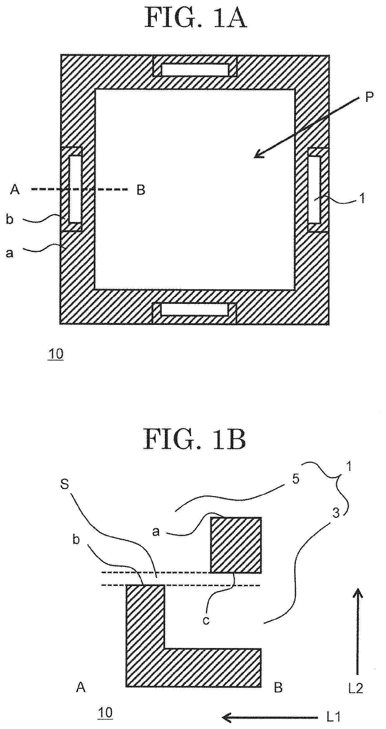
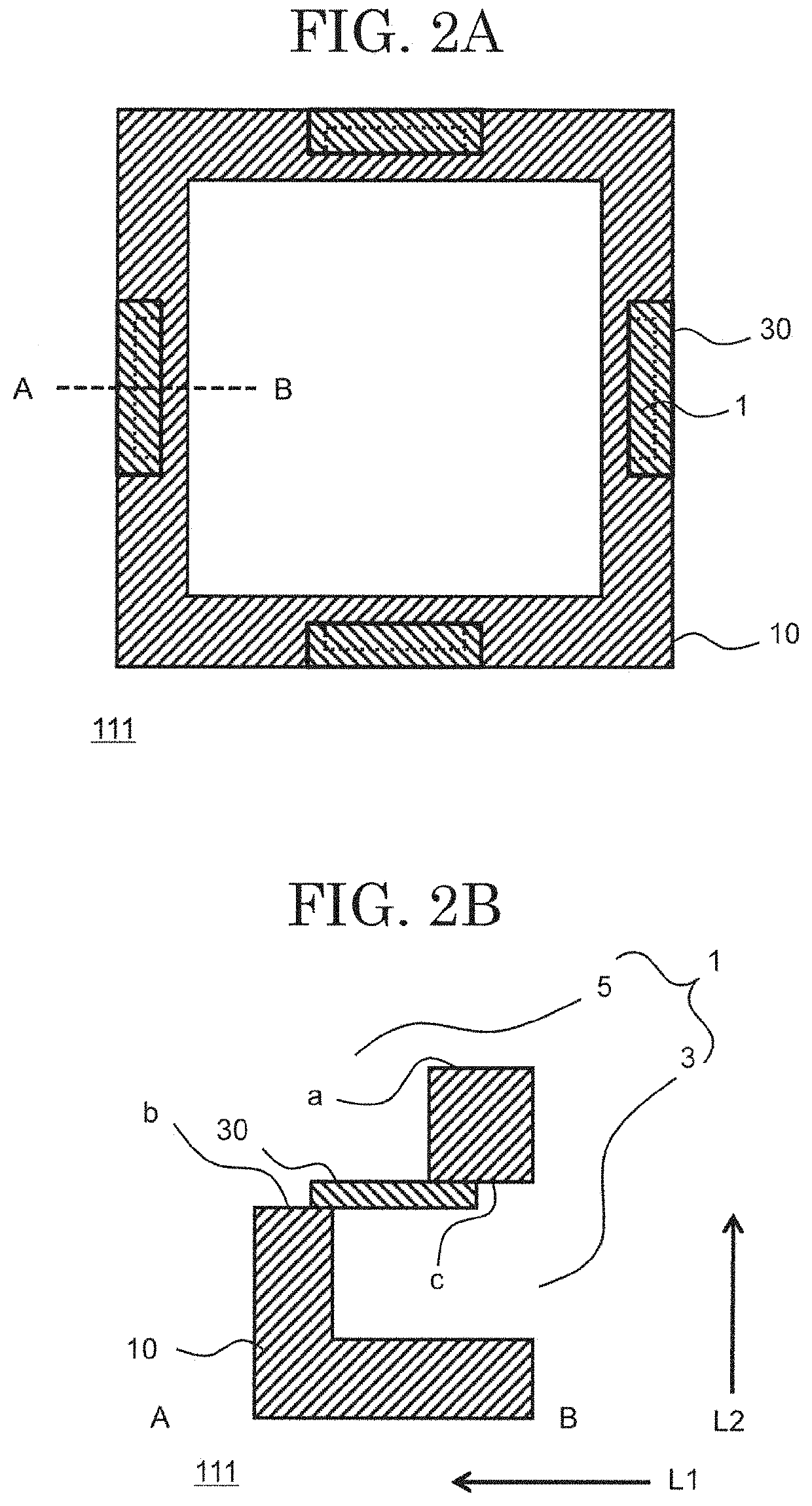
Provided is a supporting frame in which a vent hole detachably arranging a filter and to which a pellicle film for extreme ultraviolet lithography can be attached. A support frame according to an embodiment of the present invention is a support frame for arranging a pellicle film, the support frame has a through hole being made from a hole extending along a first direction, the first direction being almost parallel to a surface direction of the pellicle film, and a hole extending along a second direction, the second direction not being parallel to the first direction; and the support frame includes a filter, the filter arranged at an inside of the through hole or at an end of the through hole, and the filter is arranged apart from the pellicle film.

Description

CROSS REFERENCE TO RELATED APPLICATIONS[0001]This application is based upon and claims the benefit of priority from the prior Japanese Patent Application No. 2018-059416, filed on Mar. 27, 2018, and PCT Application No. PCT / JP2019 / 010958, filed on Mar. 15, 2019, the entire contents of which are incorporated herein by reference.FIELD[0002]A present invention relates to a photomask or a reticle used when manufacturing a semiconductor device or the like by a lithography technique (hereinafter, also referred to as a “photomask”) and a pellicle or the like which is a dustproof cover for the photomask for preventing dust from adhering thereto. In particular, the present invention relates to a support frame for a pellicle which has an ultrathin film for an extreme ultraviolet (Extreme Ultraviolet: EUV) lithography, the pellicle and a method of manufacturing the same, an exposure master plate using the same, and a method of manufacturing a semiconductor device.BACKGROUND[0003]A semiconductor...

Claims


Application Information

Patent Timeline
IPC IPC(8): G03F1/64G03F7/20
CPCG03F1/64G03F7/70191G03F7/70983G03F7/20G03F1/22H01L21/027G03F7/70866G03F7/70916
Inventor ISHIKAWA, AKIRAOKUBO, ATSUSHIONO, YOSUKEKOHMURA, KAZUO
Owner MITSUI CHEM INC
Learn More