Wireless communication system, reception device, and transmission device

a wireless communication system and reception device technology, applied in the field of wireless communication technologies, can solve the problems of insufficient degree of freedom, inability to extract each desired signal, and significant degradation of reception characteristics of terminals positioned at cell edges in cellular systems or reception characteristics of reception devices in wireless communication systems. , to achieve the effect of degrading the reception characteristics

Inactive Publication Date: 2013-11-21
SHARP KK
View PDF5 Cites 3 Cited by
  • Summary
  • Abstract
  • Description
  • Claims
  • Application Information

AI Technical Summary

Benefits of technology

[0024]According to the present invention, the degradation of the reception characteristics may be suppressed in a system that uses IA even under the circumstances in which a CSI error occurs.

Problems solved by technology

The reception characteristics of terminals positioned at a cell edge in a cellular system or the reception characteristics of reception devices in wireless communication systems may be significantly degraded due to the effects of interference (undesired signals) coming from an adjacent interference source (an adjacent cell or an adjacent wireless LAN system), the wireless systems using the same frequency band and their communication possible areas overlapping each other.
Thus, the degree of freedom is insufficient and it is impossible to extract each desired signal by eliminating interference.

Method used


Image

  • Wireless communication system, reception device, and transmission device
  • Wireless communication system, reception device, and transmission device
  • Wireless communication system, reception device, and transmission device

Examples


first embodiment

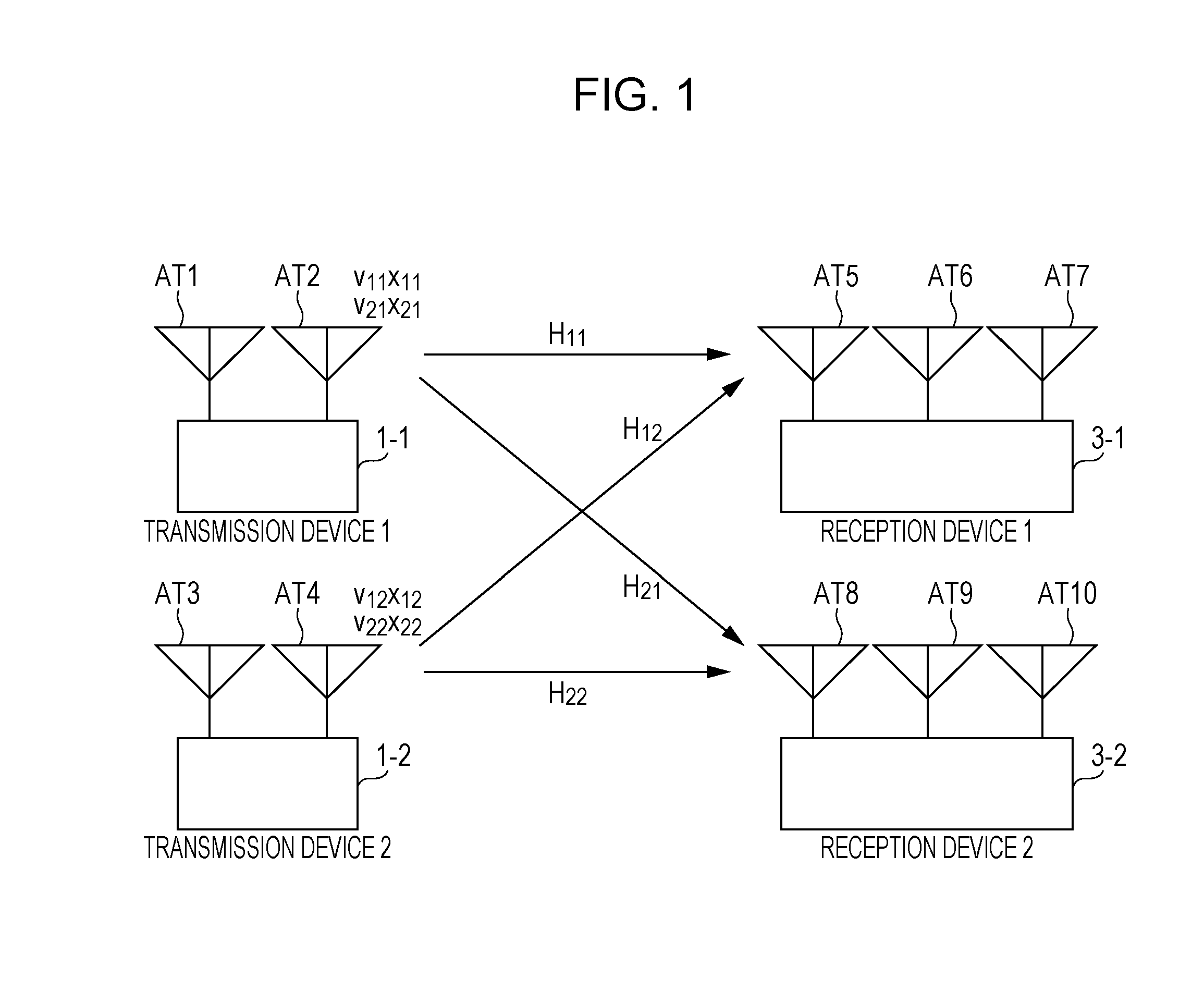
[0033]First, in the case where IA is used in a system illustrated in FIG. 1, a first embodiment of the present invention shows reception weight vectors for reducing degradation of reception characteristics under circumstances in which the CSI fed back from a reception device differs from the CSI used at the time when a signal to which IA has been applied is actually transmitted from a transmission device to the reception device, that is, under circumstances in which a CSI error occurs.

[0034]As illustrated in FIG. 1, two transmission devices each have two transmit antennas; a transmission device 1-1 has transmit antennas AT1 and 2 and a transmission device 1-2 has transmit antennas AT3 and 4. Two reception devices each have three receive antennas; a reception device 3-1 has receive antennas AT5, 6, and 7, and a reception device 3-2 has receive antennas AT8, 9, and 10. Moreover, xij denotes a signal destined for a reception device i and transmitted from a transmission device j; vij de...

second embodiment

[0075]Next, a second embodiment of the present invention will be described with reference to the drawings.

[0076]In the first embodiment, the reception weight vectors for minimizing interference occurring due to a CSI error under circumstances in which a CSI error occurs in a system in which IA is used, have been described as an example. The reception characteristics of a reception device depend not only on interference but also on thermal noise within the reception device. Thus, in contrast to the case where reception weight vectors obtained by considering only interference are used, the characteristics may be improved by using reception weight vectors obtained by considering both interference and thermal noise. In the present embodiment, a reception weight vector obtained by considering not only interference occurring due to a CSI error but also thermal noise within a reception device will be described. Specifically, the system illustrated in FIG. 6 is used as an example and a rece...


PUM


Abstract

A wireless communication system includes a plurality of transmission devices, each of which transmits signals resulting from precoding performed for a plurality of resources, and a reception device that receives at least one desired signal and a plurality of undesired signals, the number of which is greater than or equal to the degree of freedom that the plurality of resources have. The at least one desired signal and the plurality of undesired signals have been transmitted from the transmission devices. The plurality of resources is the unit of precoding. At least one of the plurality of transmission devices transmits signals on each of which precoding has been performed such that equivalent channel vectors of the plurality of undesired signals in the reception device are made to be orthogonal to a reception weight vector used in the reception device. The reception device estimates equivalent channel vectors of the plurality of undesired signals, calculates a reception weight vector by using the estimated equivalent channel vectors of the plurality of undesired signals, and extracts a desired signal by multiplying a reception signal received using the plurality of resources and the calculated reception weight vector together. The plurality of resources is the unit of precoding. As a result, in a system in which IA is used, the degradation of reception characteristics may be suppressed even under circumstances in which a CSI error occurs.

Description

TECHNICAL FIELD[0001]The present invention relates to wireless communication technologies.BACKGROUND ART[0002]The reception characteristics of terminals positioned at a cell edge in a cellular system or the reception characteristics of reception devices in wireless communication systems may be significantly degraded due to the effects of interference (undesired signals) coming from an adjacent interference source (an adjacent cell or an adjacent wireless LAN system), the wireless systems using the same frequency band and their communication possible areas overlapping each other. Such wireless communication systems are, for example, a plurality of wireless LAN systems used in rooms that are next to one another. Interference Alignment (hereinafter referred to as “IA”) has been proposed as an interference reduction method that is effective in the case where there are a plurality of transmission sources that use the same frequency band (see NPL 1 below).[0003]When IA is used, devices on...

Claims


Application Information

Patent Timeline
Patent Type & Authority Applications(United States)
IPC IPC(8): H04B7/04
CPCH04B7/0456H04B7/0417
Inventor TOH, SHINPEIHIRATA, KOZUEYAMADA, RYOTA
Owner SHARP KK
Why Eureka
Try Eureka