Imaging lens and imaging unit

a technology of imaging unit and lens, which is applied in the field of imaging lens and imaging unit, can solve the problems of difficult to obtain satisfactory resolution performance over the surroundings, difficult to reduce costs, and the failure of imaging lens in fully correcting chromatic aberration, so as to improve the efficiency of imaging and reduce the cost of restraining costs , the effect of optimizing the configuration of each lens

Active Publication Date: 2019-05-28
SONY CORP
View PDF21 Cites 2 Cited by
  • Summary
  • Abstract
  • Description
  • Claims
  • Application Information

AI Technical Summary

Benefits of technology

[0007]PTL 2 makes a proposal for a wide-angle imaging lens constituted by six lenses in five groups. The wide-angle imaging lens described in PTL 2 attains a photographing field angle of 150° or more. But the wide-angle imaging lens is constituted solely by glass lenses, and also includes a cemented lens. This contributes to advantages in terms of the chromatic aberration or sensitivity, but involves using a cementing agent or performing processing. It is therefore difficult to reduce costs. Moreover, in particular, regarding the on-vehicle cameras, in recent years, there has been rapid advancement in attempts to perform automatic operation such as a parking assistance function by white line recognition, as applications of automatic recognition techniques to the imaging units. Such cameras are requested not to suffer from changes in optical characteristics of the cameras even if temperature changes occur in tough environment where a vehicle travels. Plastic lenses allow for lower costs and smaller weight as compared to glass lenses. But the plastic lenses are subjected to significant changes in the active indexes in accordance with temperature changes. Moreover, expansion and subtraction because of large linear expansion coefficients cause changes in surface shapes, contributing to degradation in the optical characteristics. Therefore, imaging lenses constituted solely by the glass lenses have been mainly utilized so far, for the imaging lenses for the above-described applications.
[0008]PTL 3 makes a proposal for a configuration including six lenses in four groups, with a third lens group being a cemented lens of glass lenses, to restrain the changes in the optical characteristics accompanying the temperature changes. However, the configuration utilizes three glass lenses out of the six lenses. Furthermore, because the third lens group is the cemented lens of the two glass lenses, it is necessary to use the cementing agent or to perform the processing for cementing. It is therefore difficult to reduce costs. Moreover, with the cemented lens of the two plastic lenses included, there is a concern that a shape of a cemented surface changes in accordance with the temperature change, causing a cemented joint to peel off easily. Furthermore, the plastic lenses are disposed near an imaging element that serves as a source of heat generation. This makes the configurators more likely to be affected by the temperature changes.
[0009]Accordingly, there has been a desire for development of a single-focus wide-angle imaging lens that balances size reduction and a wide field angle, e.g., the photographing angle of 150° or more, and restrains changes in the optical characteristics due to the temperature changes at low costs.
[0010]It is therefore desirable to provide an imaging lens that makes it possible to achieve size reduction and cost reduction while providing a wide field angle and high image quality, and an imaging unit. Moreover, it is desirable to provide an imaging lens that makes it possible to restrain changes in optical characteristics due to temperature changes at low costs, and an imaging unit.
[0019]According to the imaging lens or the imaging unit of the embodiments of the disclosure, with the six-lens configuration as a whole, the optimization of the configuration of each lens is attained, mainly by the lens shapes and the power distribution. Hence, it is possible to achieve the size reduction and the cost reduction while providing the wide field angle and the high image quality.
[0020]According to the other imaging lens or the imaging unit of the embodiments of the disclosure, with the six-lens configuration as a whole, the optimization of the configuration of each lens is attained, mainly by the lens materials and the power distribution. Hence, it is possible to restrain the changes in the optical characteristics due to the temperature changes at the low costs.

Problems solved by technology

Accordingly, the imaging lens fails in fully correcting a chromatic aberration.
It is difficult to obtain the satisfactory resolution performance over the surroundings.
It is therefore difficult to reduce costs.
Moreover, expansion and subtraction because of large linear expansion coefficients cause changes in surface shapes, contributing to degradation in the optical characteristics.
It is therefore difficult to reduce costs.
Moreover, with the cemented lens of the two plastic lenses included, there is a concern that a shape of a cemented surface changes in accordance with the temperature change, causing a cemented joint to peel off easily.
This makes the configurators more likely to be affected by the temperature changes.

Method used


Image

  • Imaging lens and imaging unit
  • Imaging lens and imaging unit
  • Imaging lens and imaging unit

Examples


application example

[3. Application Example to Imaging Unit]

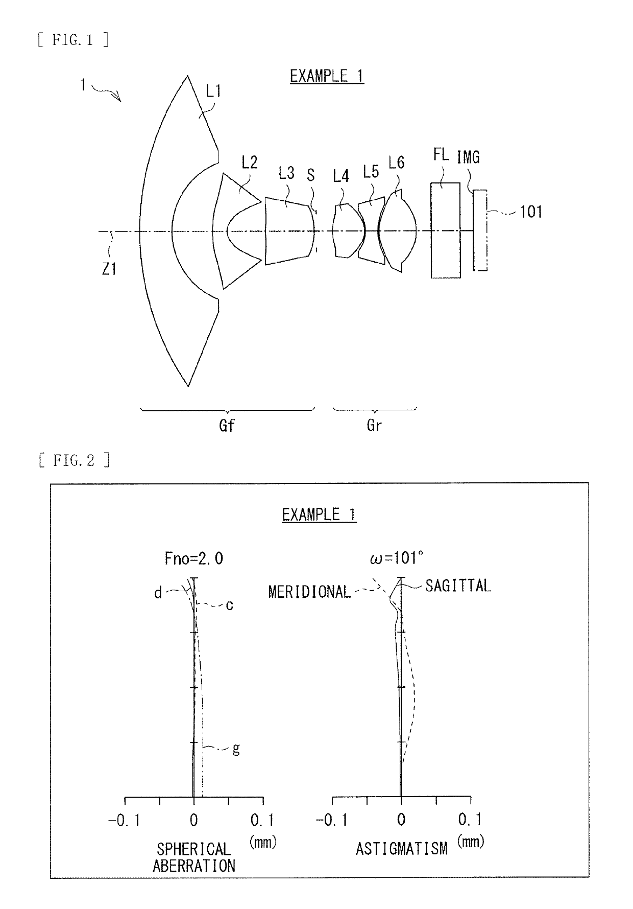
[0070]The imaging lens according to this embodiment is applicable to, for example, an imaging unit such as an on-vehicle camera, a monitoring camera, and a camera for a mobile device. In the case of the application to the imaging unit, as illustrated in FIG. 1, the imaging element 101 such as CCD (Charge Coupled Devices) and CMOS (Complementary Metal Oxide Semiconductor) is disposed in the vicinity of the image plane IMG of the imaging lens. The imaging element 101 outputs an imaging signal (an image signal) that corresponds to an optical image formed by the imaging lens. In this case, as illustrated in the figures such as FIG. 1, for example, a filter such as an infrared ray cutoff filter and a low pass filter may be disposed between the sixth lens L6 to and the image plane IMG. In addition, optical members such as sealing glass for protection of the imaging element may be disposed.

[0071]FIGS. 11 and 12 provide a configuration example of on-v...

numerical example 1

[0087][Table 1] summarizes lens data of Numerical Example 1 in which specific numerical values are applied to the imaging lens 1 illustrated in FIG. 1. In the imaging lens 1, both sides of each of the second lens L2 to the sixth lens L6 are the aspherical surfaces. [Table 2] summarizes values of the aspherical surface coefficients A4, A6, A8, A10, A12, A14, and A16 in the aspherical surfaces, together with values of the conical coefficient κ. Moreover, [Table 3] summaries the focal length f of the entire system, the F number Fno, the half field angle ω, and a value of a lens total length.

[0088]In this Numerical Example 1, the first lens L1 is a glass lens. The second lens L2 to the sixth L6 are all plastic lenses.

[0089]

TABLE 1Example 1SurfacenumberRiDiNivi 114.6001.3001.5891361.25 23.7281.573 3(ASP)6.9980.5651.5444256 4(ASP)1.0091.542 5(ASP)22.2681.9001.6423.5 6(ASP)−3.4540.090 7(STO)∞0.650 8(ASP)3.3191.2531.5444256 9(ASP)−1.3550.04010(ASP)−1.7060.4801.6423.511(ASP)2.4700.04012(ASP)...

numerical example 2

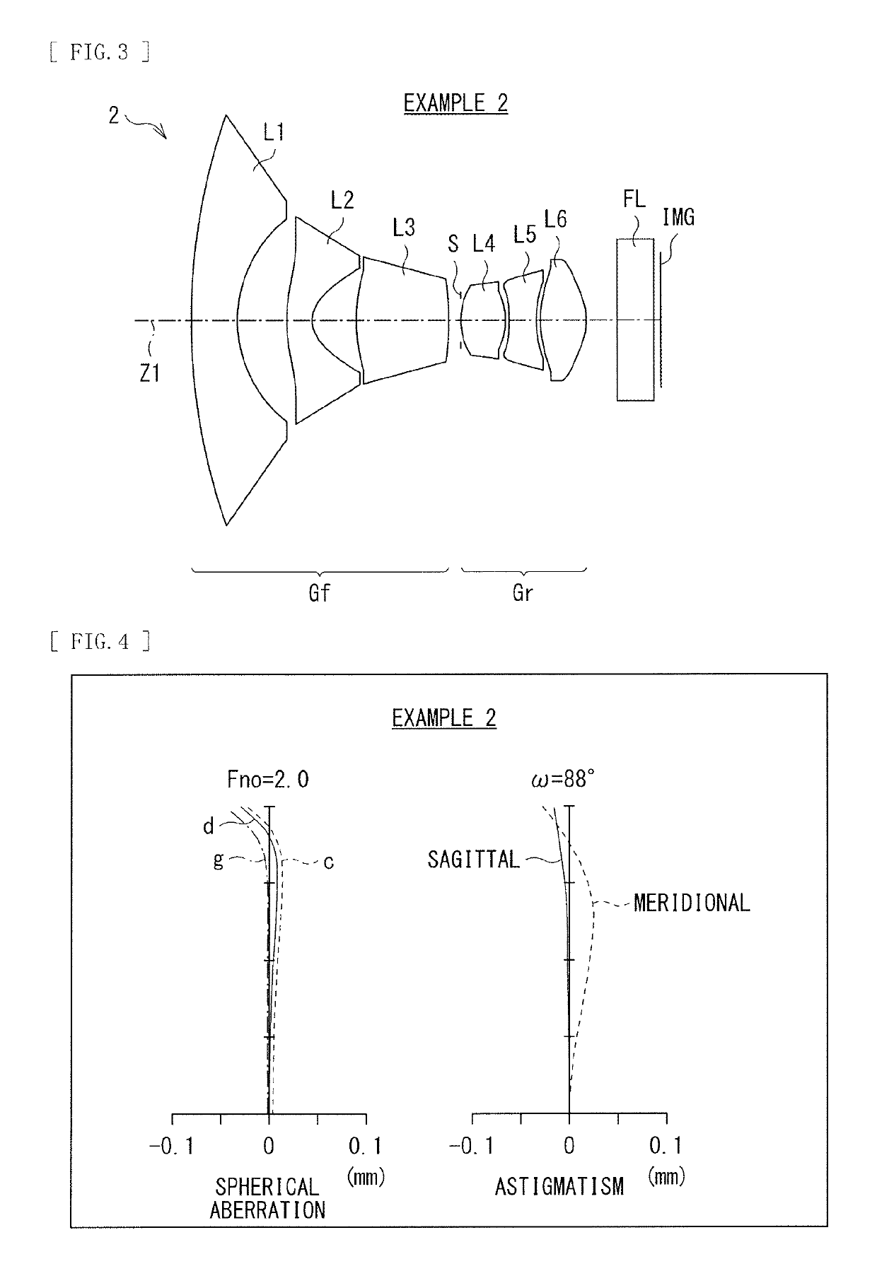
[0094][Table 4] summarizes lens data of Numerical Example 2 in which specific numerical values are applied to the imaging lens 2 illustrated in FIG. 3. In the imaging lens 2, both sides of each of the second lens L2 to the sixth lens L6 are the aspherical surfaces. [Table 5] summarizes the values of the aspherical surface coefficients A4, A6, A8, A10, A12, A14, and A16 in the aspherical surfaces, together with the values of the conical coefficient κMoreover. [Table 6] summarizes the focal length f of the entire system, the F number Fno, the half field angle ω, and the value of the lens total length.

[0095]In this Numerical Example 2, the first lens L1 is a glass lens. Moreover, the second lens L2 to the sixth lens L6 are all plastic lenses.

[0096]

TABLE 4Example 1SurfacenumberRiDiNivi 120.2211.3001.5891361.25 24.0491.384 3(ASP)4.4230.6761.5444256 4(ASP)0.8621.207 5(ASP)4.6682.5901.6423.5 6(ASP)−21.6940.368 7(STO)∞0.000 8(ASP)2.0341.2061.5444256 9(ASP)−1.8340.14710(ASP)−2.8720.7191.6423...


PUM


Abstract

An imaging lens according to the disclosure includes a negative front group, a stop, and a positive rear group. The front group includes a negative first lens having a meniscus shape with a convex surface facing the object side, a negative second lens having the meniscus shape with a convex surface facing the object side, and a positive third lens having a biconvex shape. The rear group includes a positive fourth lens, a negative fifth lens with a concave surface facing the image side, and a positive sixth lens.

Description

TECHNICAL FIELD[0001]The disclosure relates to an imaging lens and an imaging unit that are suitable for, for example, on-vehicle cameras, monitoring cameras, and cameras for mobile devices.BACKGROUND ART[0002]In recent years, imaging units such as on-vehicle cameras, monitoring cameras, and cameras for mobile devices have been widely spreading. These imaging units are requested to ensure a wide field angle, while achieving satisfactory resolution performance of the surroundings, with a small size and at low costs. Examples of wide-angle imaging lenses that satisfy such requests include those as described in the following PTLs 1 to 3.CITATION LISTPatent Literature[0003]PTL 1: Japanese Unexamined Patent Application Publication No. 2013-3545[0004]PTL 2: Japanese Unexamined Patent Application Publication No. 2014-197131[0005]PTL 3: Japanese Unexamined Patent Application Publication No. 2014-89349SUMMARY OF THE INVENTION[0006]PTL 1 makes a proposal for a wide-angle imaging lens constitu...

Claims


Application Information

Patent Timeline
Patent Type & Authority Patents(United States)
IPC IPC(8): G02B3/02H04N5/225H04N5/232G02B13/06G02B13/04G02B9/62G02B13/00G02B7/02
CPCG02B13/06G02B9/62G02B13/04H04N5/23238H04N5/2254G02B13/0045G02B7/028H04N23/698
Inventor MATSUNAGA, SHIGEHIKO
Owner SONY CORP
Why Eureka
Try Eureka