Fuel cell system

a fuel cell and system technology, applied in the direction of fuel cells, motive system fuel cells, reactant parameter control, etc., can solve the problems of shortening the hydrogen which can be used for power generation by increasing the amount of fuel gas to be consumed, and degrading the fuel cell stack, etc., to increase the hydrogen concentration at the outlet port of the ejector, and suppress the shortage of hydrogen

Active Publication Date: 2022-08-11
TOYOTA JIDOSHA KK
View PDF5 Cites 2 Cited by
  • Summary
  • Abstract
  • Description
  • Claims
  • Application Information

AI Technical Summary

Benefits of technology

[0009]It is occasionally not desirable to make the ejector outlet port pressure more than a predetermined upper limit value. Even in such a situation, it is necessary to suppress a shortage of hydrogen that can be used for power generation by the fuel cell stack. In the configuration described above, the control device switches the exhaust-drainage valve to the open state when the estimated circulation flow rate is lower than the required circulation flow rate and the required upper limit value that is specified based on the required load, is equal to or more than the predetermined upper limit value. When the exhaust-drainage valve is switched to the open state, a nitrogen gas contained in the fuel off gas in the gas-liquid separator is exhausted to the outside through the exhaust-drainage path. Therefore, the hydrogen concentration at the outlet port of the ejector can be increased. Also with such a configuration, it is possible to suppress a shortage of hydrogen that can be used for power generation by the fuel cell stack.

Problems solved by technology

In general, when there is a shortage of a fuel gas to be supplied to a fuel cell stack, hydrogen which can be used for power generation by the fuel cell stack may become short, and the fuel cell stack may be degraded.
When a large amount of fuel gas is supplied to the fuel cell stack in advance, however, the amount of fuel gas to be consumed may be increased to reduce the fuel efficiency.
This increases the amount of hydrogen to be supplied to the fuel cell stack, and increases the hydrogen concentration at the outlet port of the ejector.

Method used


Image

  • Fuel cell system
  • Fuel cell system
  • Fuel cell system

Examples


first modification

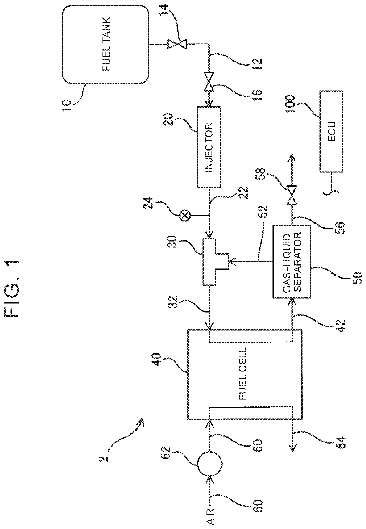
[0055]The fuel cell system 2 may include at least one of a pressure sensor provided in the third fuel supply path 32 and a pressure sensor provided in the gas circulation path 52.

[0056]With such a configuration, the precision in calculating the pressure difference between the ejector inlet port pressure and the ejector outlet port pressure can be improved.

second modification

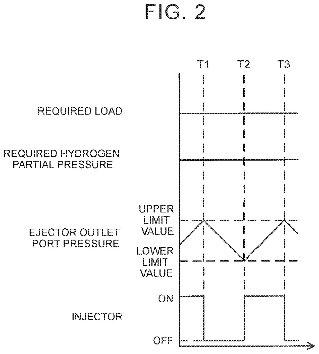
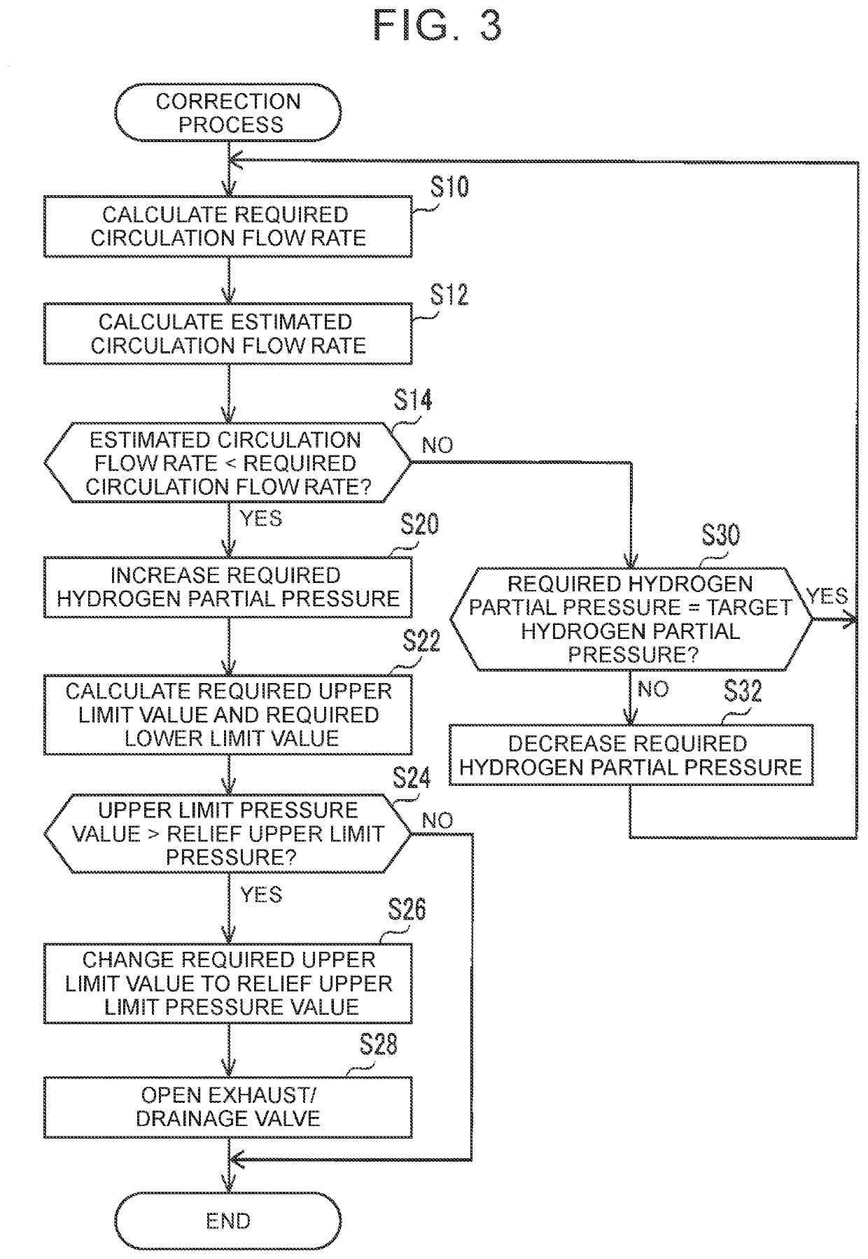
[0057]Steps S24 and S26 in FIG. 3 may be omitted.

third modification

[0058]The ECU 100 may determine whether a difference obtained by subtracting the estimated circulation flow rate from the required circulation flow rate is more than a predetermined flow rate after step S14 in FIG. 3, and execute the processes in and after step S20 only when the difference is more than the predetermined flow rate.

[0059]The technical elements described herein or illustrated in the drawings exhibit technical usefulness alone or in various combinations, and are not limited to the embodiment. In addition, the technology described herein or illustrated in the drawings may achieve a plurality of objects at the same time, and has technical usefulness by achieving one of the objects itself


PUM

PropertyMeasurementUnit
pressure difference detectionaaaaaaaaaa
pressureaaaaaaaaaa
circulation flow rateaaaaaaaaaa

Abstract

A fuel cell system includes a fuel cell stack, a fuel gas supply path, an injector, an ejector, a circulation path, a pressure difference detection unit that detects a pressure difference between an ejector inlet port pressure and an ejector outlet port pressure, and a control device. The control device calculates a required circulation flow rate that is required for a fuel off gas supplied from the fuel cell stack to the ejector, based on a required load for the fuel cell stack, calculates an estimated circulation flow rate that is an estimated flow rate of the fuel off gas supplied from the fuel cell stack to the ejector, based on the required load and the pressure difference, and increases the flow rate of a fuel gas supplied from the injector to the fuel cell stack when the estimated circulation flow rate is lower than the required circulation flow rate.

Description

CROSS-REFERENCE TO RELATED APPLICATION[0001]This application claims priority to Japanese Patent Application No. 2021-018585 filed on Feb. 8, 2021, incorporated herein by reference in its entirety.BACKGROUND1. Technical Field[0002]The technology disclosed herein relates to a fuel cell system.2. Description of Related Art[0003]Japanese Unexamined Patent Application Publication No. 2019-67708 (JP 2019-67708 A) discloses a fuel cell system that includes a fuel cell stack, a fuel gas supply path through which a fuel gas is supplied to the fuel cell stack, an injector provided in the fuel gas supply path, an ejector provided in the fuel gas supply path and provided between the injector and the fuel cell stack, a circulation path through which a fuel off gas discharged from the fuel cell stack is supplied to the ejector, and a control device.SUMMARY[0004]In general, when there is a shortage of a fuel gas to be supplied to a fuel cell stack, hydrogen which can be used for power generation b...

Claims


Application Information

Patent Timeline
Patent Type & Authority Applications(United States)
IPC IPC(8): H01M8/04746H01M8/04082H01M8/04119H01M8/04089H01M8/0438
CPCH01M8/04761H01M8/04201H01M2250/20H01M8/04097H01M8/0438H01M8/04156H01M8/04H01M8/04089H01M8/0662H01M8/04432H01M8/04164H01M8/04388Y02E60/50
Inventor MIZUNO, NOBUKAZUHASEGAWA, SHIGEKIHAGA, MIYUTANAKA, SEIICHI
Owner TOYOTA JIDOSHA KK
Why Eureka
Try Eureka