Dynamic-map constructing method, dynamic-map constructing system, and moving terminal

a dynamic map and building system technology, applied in vehicle position indication, navigation instruments, instruments, etc., can solve the problems of insufficient network bandwidth, inability to consider efficient information collection, and increase the overall amount of communication between roadside devices and vehicles, so as to reduce the shortage of network band

Active Publication Date: 2020-05-26
PANASONIC INTELLECTUAL PROPERTY CORP OF AMERICA
View PDF13 Cites 0 Cited by
  • Summary
  • Abstract
  • Description
  • Claims
  • Application Information

AI Technical Summary

Benefits of technology

[0011]One non-limiting and exemplary embodiment provides a dynamic-map constructing method, a dynamic-map constructing system, and a moving terminal that can suppress a shortage of a network band.
[0013]The dynamic-map constructing method, the dynamic-map constructing system, and the moving terminal according to the present disclosure can suppress a shortage of a network band.

Problems solved by technology

In Patent Document 1, however, the sensor information that is collected also includes unwanted information, and no consideration is given to efficient information collection.
Thus, in the methods disclosed in Patent Documents 1 and 2, for example, the overall amount of communication between the roadside devices and the vehicles increases, thus the network bandwidth becomes insufficient

Method used


Image

  • Dynamic-map constructing method, dynamic-map constructing system, and moving terminal
  • Dynamic-map constructing method, dynamic-map constructing system, and moving terminal
  • Dynamic-map constructing method, dynamic-map constructing system, and moving terminal

Examples


first embodiment

[0052][1.1 Configuration of Dynamic-Map Constructing System]

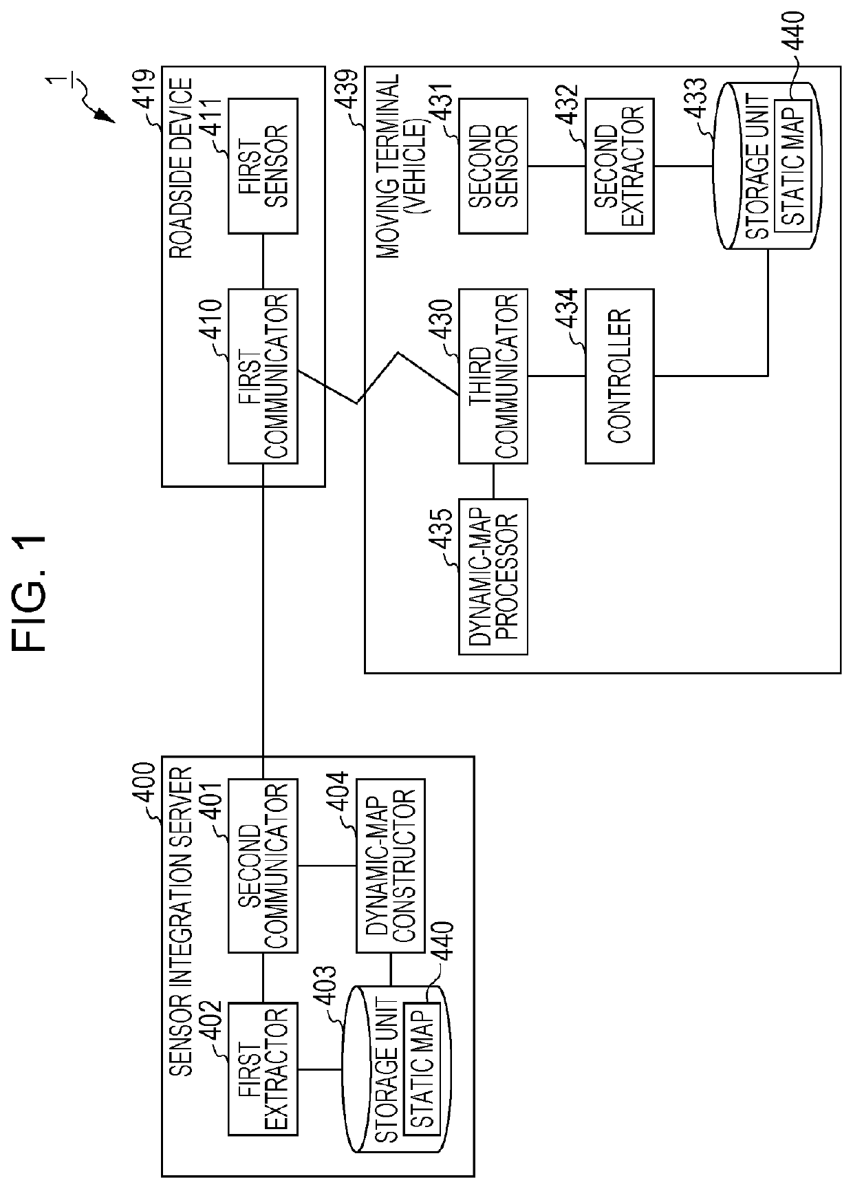
[0053]FIG. 1 is a block diagram illustrating one example of the configuration of a dynamic-map constructing system 1 according to the first embodiment.

[0054]The dynamic-map constructing system 1 is a system that constructs an integrated dynamic map in which areas on a static map and information indicating objects that exist at actual places corresponding to the areas are associated with each other. The static map is a map including static information whose positions do not vary on a long-term basis. Examples include buildings, roads, and traffic lights. Also, examples of the objects that exist at actual places include position-varying moving objects, such vehicles, people, or bicycles, or non-moving objects, such as standing signs that are temporarily placed. Information indicating presences of such objects is referred to as “dynamic information”. Moving terminals, such as vehicles, can recognize actual road situations and ...

second embodiment

[0125]A second embodiment will be described with reference to FIGS. 13 to 16.

[0126]First, the configuration of a dynamic-map constructing system 2 according to the second embodiment will be described with reference to FIG. 13.

[0127]FIG. 13 is a block diagram illustrating one example of the configuration of the dynamic-map constructing system 2 according to the second embodiment.

[0128]The dynamic-map constructing system 2 according to the present embodiment differs from the dynamic-map constructing system 1 according to the first embodiment in that a moving terminal 800 is provided instead of the moving terminal 439. Since other constituent elements of the dynamic-map constructing system 2 are substantially the same as those in the first embodiment, descriptions thereof are not given hereinafter. In addition, the moving terminal 800 differs from the moving terminal 439 according to the first embodiment in that a controller 834 is provided instead of the controller 434. Since other co...

third embodiment

[0143]A third embodiment will be described with reference to FIGS. 17 to 19.

[0144]First, the configuration of a dynamic-map constructing system 3 according to the third embodiment will be described with reference to FIG. 17.

[0145]FIG. 17 is a block diagram illustrating one example of the configuration of the dynamic-map constructing system 3 according to the third embodiment.

[0146]The dynamic-map constructing system 3 according to the present embodiment differs from the dynamic-map constructing system 1 according to the first embodiment in that a moving terminal 1100 is provided instead of the moving terminal 439. Since other constituent elements of the dynamic-map constructing system 3 are substantially the same as those in the first embodiment, descriptions thereof are not given hereinafter. In addition, the moving terminal 1100 differs from the moving terminal 439 according to the first embodiment in that a controller 1134 is provided instead of the controller 434. Since other co...


PUM


Abstract

A roadside device transmits first detection data obtained by a first sensor to a server. The server extracts an unobservable area that is a blind spot of the first sensor, based on the first detection data, and transmits unobservable-area information indicating the unobservable area to a moving terminal. The moving terminal extracts, based on second detection data obtained by a second sensor, second dynamic information indicating an object that exists in a sensing range of the second sensor, and determines whether or not an overlapping area where the unobservable area indicated by the unobservable-area information and the sensing range of the second sensor overlap each other exists. Upon determining that the overlapping area exists, the moving terminal transmits, to the server, third dynamic information that is included in the second dynamic information and that indicates an object that exists in the overlapping area.

Description

BACKGROUND1. Technical Field[0001]The present disclosure relates to a dynamic-map constructing method for constructing a dynamic map in which areas on a static map and dynamic information indicating objects, such as vehicles, people, or the like, that exist at actual places corresponding to the areas are associated with each other, a dynamic-map constructing system for constructing the dynamic map, and a moving terminal.2. Description of the Related Art[0002]Recent years have seen advances in development of technology for aiding safe driving and technology for realizing automatic driving. In the development of the technologies, a dynamic map has been proposed for a moving terminal (vehicle) to recognize dynamic information about the position and the moving speed of a vehicle, person, bicycle, or the like in the surroundings of the moving terminal, the state of a traffic light, and so on. The dynamic map is, for example, a map in which the dynamic information in the surroundings of a...

Claims


Application Information

Patent Timeline
Patent Type & Authority Patents(United States)
IPC IPC(8): G08G1/16G08G1/01G08G1/13G01C21/32
CPCG08G1/0112G08G1/0145G08G1/0116G08G1/13G01C21/32G08G1/166G01C21/3415G01C21/3841G01C21/3893
Inventor KONISHI, KAZUNOBUMURAMOTO, EIICHIYONEDA, TAKAHIROOHNISHI, RYOTASHIMOTSUMA, YUTA
Owner PANASONIC INTELLECTUAL PROPERTY CORP OF AMERICA
Why Eureka
Try Eureka