Internal combustion engine

a combustion engine and internal combustion technology, applied in the direction of engine components, lubrication elements, auxiliaries, etc., can solve the problems of shortage of lubrication, impede the smooth flow of oil into the oil drop hole, etc., to suppress the shortage of lubrication oil and facilitate the flow of lubrication oil

Active Publication Date: 2022-04-28
NISSAN MOTOR CO LTD
View PDF5 Cites 1 Cited by
  • Summary
  • Abstract
  • Description
  • Claims
  • Application Information

AI Technical Summary

Benefits of technology

[0004]An object of this invention is to facilitate the flow of lubrication oil into the oil dropping hole to suppress a shortage in the lubrication oil of the member such as a gear.

Problems solved by technology

In such a configuration, traveling conditions of the vehicle such as acceleration and deceleration can cause biasing in the distribution of the oil accumulated in the base part of the cylinder head, hindering a smooth flow of the oil into the oil dropping hole.
As a result, if the oil flowing into the oil dropping hole is to be used for lubrication purpose of a member such as a gear, shortage of lubrication may occur.

Method used


Image

  • Internal combustion engine
  • Internal combustion engine
  • Internal combustion engine

Examples


first embodiment

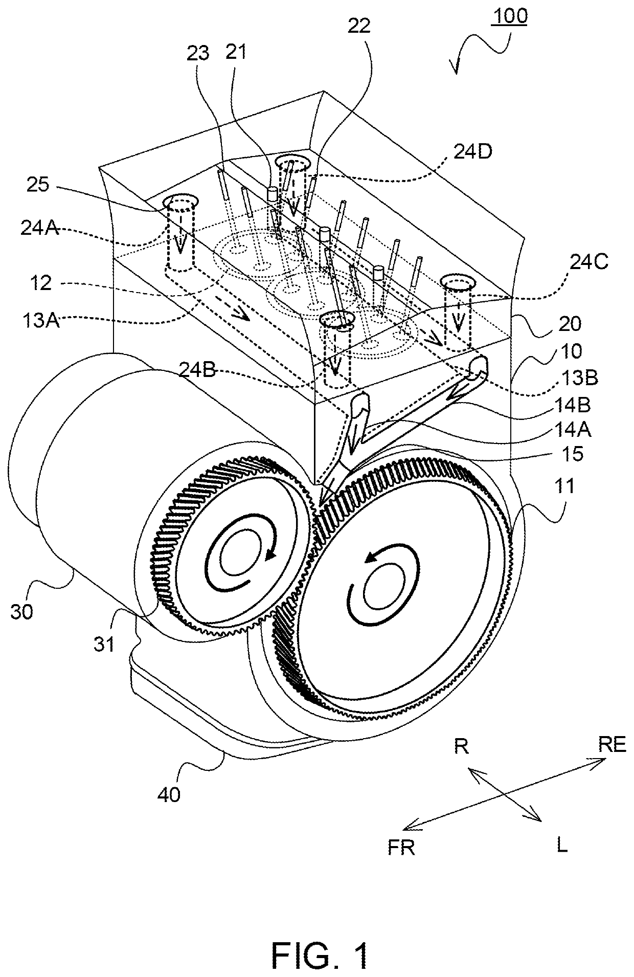
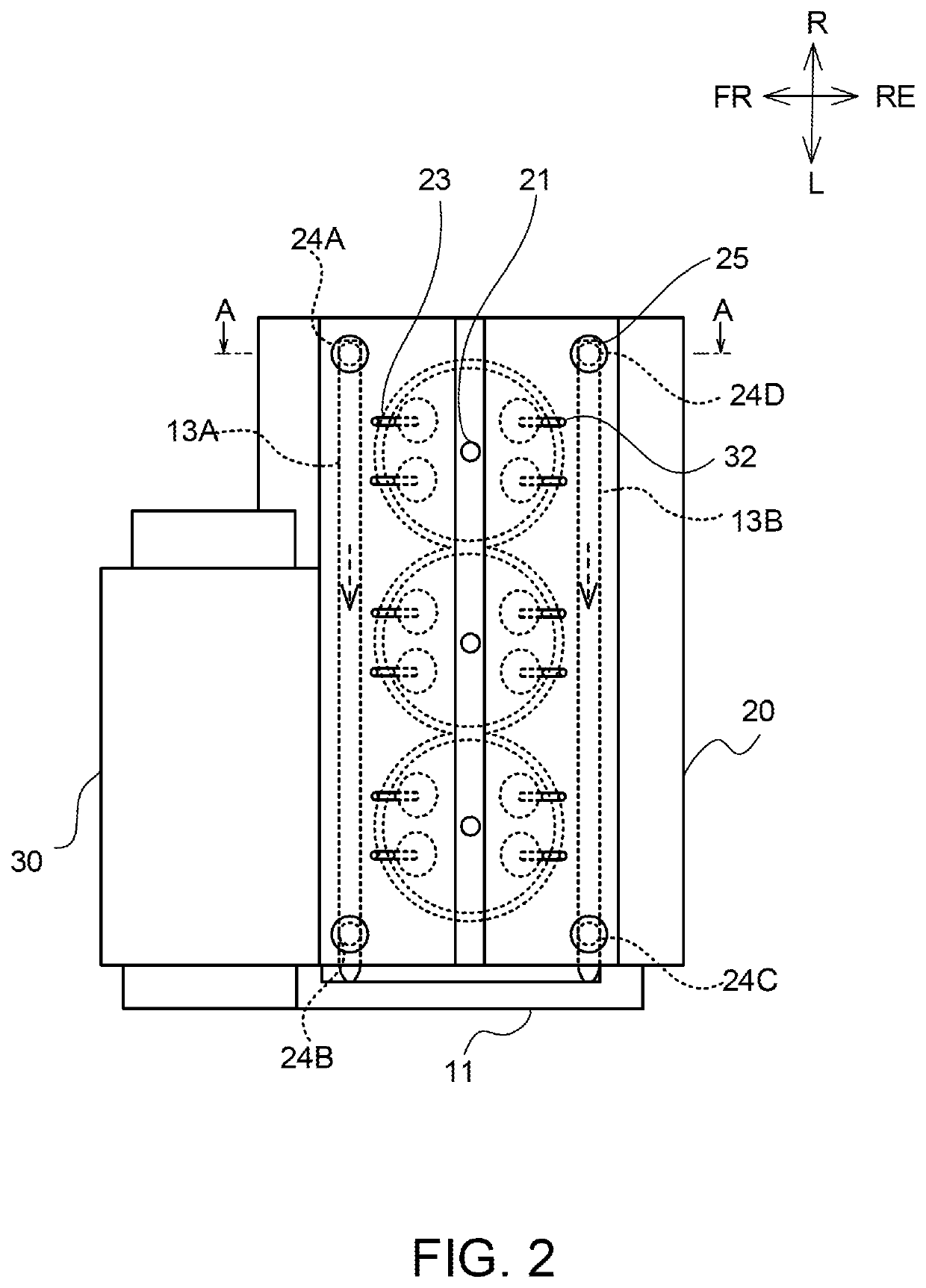
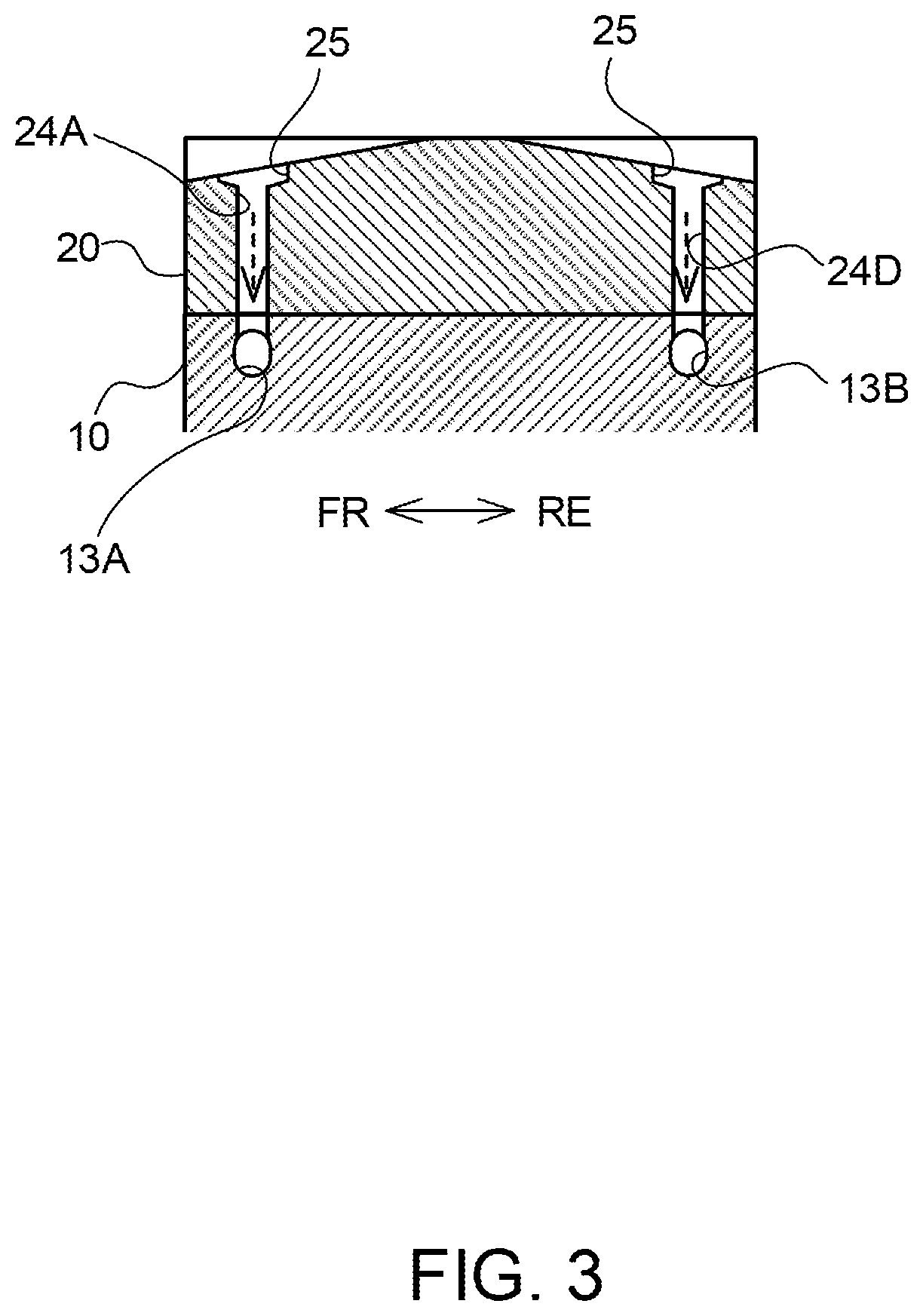
[0012]FIG. 1 shows a perspective view of the internal combustion engine 100 of the first embodiment.

[0013]The internal combustion engine 100 consists of its main body having a cylinder block 10 and an cylinder head 20, and, additionally a generator 30. In the following descriptions, the internal combustion engine 100 is referred simply to as the engine 100. The engine 100 is generally mounted on a vehicle, wherein the engine 100 provides driving power to the generator 30 whose output may be supplied to batteries and motors (not shown in the figure). The output from the generator 30 can also be used for motoring the engine 100.

[0014]The cylinder block 10 has a crankshaft having a driving gear 11 on its end, and the generator 30 has a transmission gear 31 on the end of the rotor shaft. These two gears—the driving gear 11 and the transmission gear 31—are configured to engage each other. This configuration enables the rotational driving force generated by the engine 100 to be transmitte...

third embodiment

[0066]In the first embodiment, a configuration is described wherein the second oil channels (14A and 14B) and the third oil channel (15) are arranged to the discharging end (driving gear 11 side) of the first oil channel 13A and 13B. However, the preferred configuration is not limited to this. In this embodiment, an arrangement is described wherein the second oil channels 14A, 14B and the third oil channel 15 are omitted.

[0067]FIG. 5 shows a perspective view of the engine 100 of the third embodiment. In comparison with the engine 100 of the first embodiment, the engine 100 of the third embodiment is characterized by the omission of the second oil channels 14A, 14B and the third oil channel 15. The discharging ends of the first oil channels 13A and 13B have openings above the driving gear 11. Thus, the oil exiting from the first oil channels 13A and 13B drop down onto the driving gear 11.

[0068]The following effects can be obtained from the engine 100 of the third embodiment.

[0069]Sin...


PUM


Abstract

Provided is an internal combustion engine having an oil circulating structure wherein oil used to lubricate valve operating members in the cylinder head drops onto an oil pan, and the oil accumulated therein is drawn up to the cylinder head again. Each on corners of the squire bottom face inside the cylinder head of the internal combustion engine, an oil dropping hole is provided to allow the oil used to lubricate valve operating members to flow thereinto. Also provided is an oil channel communicating with one or more of the oil dropping hole at the bottom thereof to guide the oil toward the driving gear transmitting the driving force of the engine.

Description

TECHNICAL FIELD[0001]The present invention relates to an internal combustion engine.BACKGROUND ART[0002]In general, inside the cylinder head of an internal combustion engine, lubrication oil is supplied to a valve operating member, such as an intake valve and an exhaust valve, and the supplied oil flows into an oil dropping hole provided inside in the cylinder head. After flowing into the oil dropping hole, the lubrication oil flows down through the cylinder block located in the base part of the cylinder head and finally drops onto an oil pan. The lubrication oil accumulated in the oil pan is then pumped up by a pump and returned to the cylinder head for circulation. (for example, JPS62-99607A)SUMMARY OF INVENTION[0003]Let us consider an engine mounted on a vehicle, wherein the oil dropping hole is provided in the vicinity of the sides of the cylinder head as shown in JPS62-99607A. In such a configuration, traveling conditions of the vehicle such as acceleration and deceleration can...

Claims


Application Information

Patent Timeline
Patent Type & Authority Applications(United States)
IPC IPC(8): F01M9/08F01M11/02F01M9/10
CPCF01M9/08F01M11/02F01M2011/023F01M9/105F01M9/106F01M9/108F01M9/10
Inventor OTANI, MASAYUKISATOU, NOBUHIKO
Owner NISSAN MOTOR CO LTD
Why Eureka
Try Eureka