Hybrid vehicle

a hybrid vehicle and hybrid technology, applied in the direction of machines/engines, gearing details, transportation and packaging, etc., can solve the problem of shortening the driving force during reverse travel

Active Publication Date: 2020-12-17
TOYOTA JIDOSHA KK
View PDF0 Cites 0 Cited by
  • Summary
  • Abstract
  • Description
  • Claims
  • Application Information

AI Technical Summary

Benefits of technology

[0009]With the hybrid vehicle of the above aspect, during forward travel, the change-over valve is switched into the first state, and oil discharged from the discharge port of the first oil pump and the discharge port of the second oil pump is supplied to the components to be cooled or lubricated via the oil passage. On the other hand, during reverse travel, the change-over valve is switched into the second state, and oil discharged from the second oil pump is supplied via the oil passage to the discharge port of the first oil pump, so the first oil pump can be operated as a hydraulic motor. In this way, the change-over valve is switched between the first state and the second state, so the first oil pump can be operated as a hydraulic motor only during reverse travel.

Problems solved by technology

Therefore, since the driving force of the engine is not used during reverse travel, shortage of driving force can occur during reverse travel.

Method used


Image

  • Hybrid vehicle
  • Hybrid vehicle
  • Hybrid vehicle

Examples


first embodiment

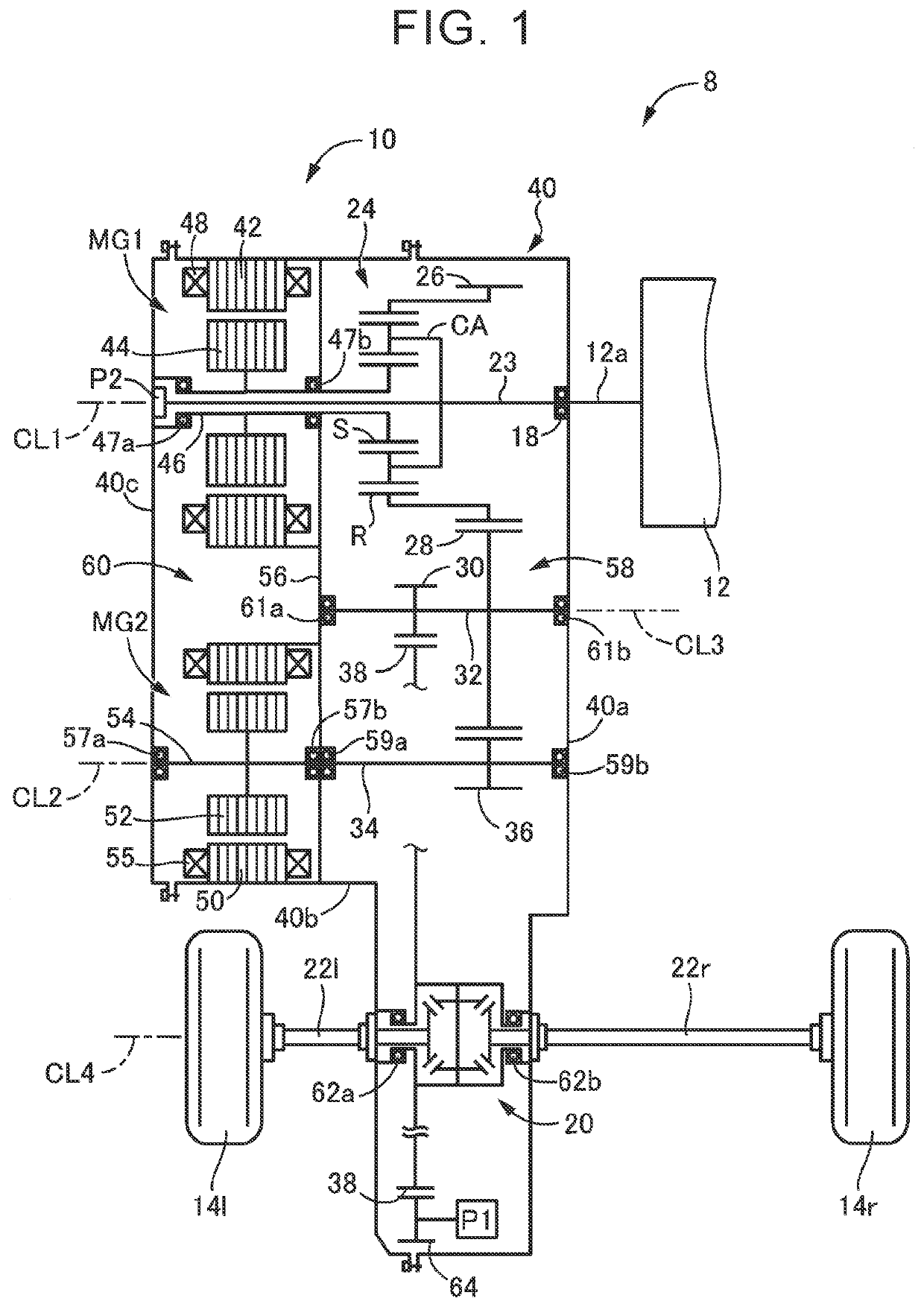
[0034]FIG. 1 is a skeletal diagram that schematically shows the configuration of a hybrid vehicle 8 (hereinafter, referred to as vehicle 8) of the disclosure. The vehicle 8 includes a vehicle drivetrain 10 (hereinafter, referred to as drivetrain 10) between an engine 12 and a pair of right and left drive wheels 14r, 14l (referred to as drive wheels 14 when not distinguished from each other). The drivetrain 10 is used in a front-engine, front-wheel drive (FF) hybrid vehicle. The drivetrain 10 is a hybrid drivetrain that transmits a power output from at least one of the engine 12 or a second electric motor MG2, which are driving force sources, to the right and left drive wheels 14r, 14l via a differential gear set 20, a pair of right and left axles 22r, 22l, and other components.

[0035]As shown in FIG. 1, the drivetrain 10 includes an input shaft 23, a planetary gear train 24, a first electric motor MG1, an output gear 26, a power transmission shaft 34, the second electric motor MG2, a...

third embodiment

[0091]FIG. 6 is a table that shows modes of combinations of components to be cooled or lubricated, other than the differential gear-driven pump P1, during reverse travel according to a In FIG. 6, “GEARS AND BEARINGS IN GEAR CHAMBER” correspond to the gears in the gear chamber 58 and the bearings in the gear chamber 58, which are the components to be cooled or lubricated, “MG” corresponds to the first electric motor MG1 and the second electric motor MG2, which are the components to be cooled or lubricated, and “GEARS AND BEARINGS OF PLANETARY GEAR TRAIN” correspond to the gears and bearings of the planetary gear train 24, which are the components to be cooled or lubricated. In FIG. 6, “SUPPLIED” indicates that oil is supplied during reverse travel, and “NOT SUPPLIED” indicates that oil is not supplied during reverse travel.

[0092]Mode 1 shown in FIG. 6 corresponds to the mode in which, during reverse travel, oil is supplied to the differential gear-driven pump P1, but oil is not supp...

fifth embodiment

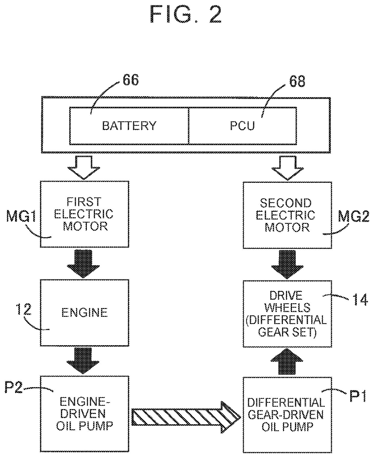
[0109]FIG. 12 is the schematic configuration of a hybrid vehicle 200 (hereinafter, referred to as vehicle 200) according to the disclosure. The vehicle 200 includes the engine 12 that serves as a driving force source, the first electric motor MG1 connected to the engine 12 such that power is transmittable, the second electric motor MG2 that serves as a driving force source, and a clutch C inserted between the engine 12 and the differential gear set 20. The vehicle 200 includes the differential gear-driven pump P1 and the engine-driven pump P2. The differential gear-driven pump P1 is driven by the differential ring gear 38 (see FIG. 1, or the like) of the differential gear set 20. The engine-driven pump P2 is driven by the engine 12.

[0110]The vehicle 200 is configured to be able to shift into the hybrid drive mode (HV mode) and the motor drive mode (EV mode). In the hybrid drive mode (HV mode), the vehicle 200 travels by using the engine 12 and the second electric motor MG2. In the m...


PUM


Abstract

A hybrid vehicle including an engine, a drive motor, a first oil pump, and a second oil pump is configured to, during forward travel, supply components to be cooled or lubricated with oil discharged from a discharge port of the first oil pump and a discharge port of the second oil pump via an oil passage, while the hybrid vehicle is configured to, during reverse travel, compensate for a driving force by supplying oil discharged from the discharge port of the second oil pump to the discharge port of the first oil pump via the oil passage to cause the first oil pump to operate as a hydraulic motor.

Description

CROSS-REFERENCE TO RELATED APPLICATION[0001]This application claims priority to Japanese Patent Application No. 2019-109120 filed on Jun. 11, 2019, incorporated herein by reference in its entirety.BACKGROUND1. Technical Field[0002]The disclosure relates to provision of a driving force during reverse travel in a hybrid vehicle that uses an engine and a motor as driving force sources.2. Description of Related Art[0003]A hybrid vehicle that includes an engine and a motor as driving force sources and that transmits a driving force from the driving force sources to drive wheels via an output part is known. This is, for example, the hybrid vehicle described in Japanese Unexamined Patent Application Publication No. 2017-137991 (JP 2017-137991 A). The hybrid vehicle suggested in JP 2017-137991 A includes a first oil pump and a second oil pump. The first oil pump is mechanically driven with the rotation of an output part. The second oil pump is driven by a rotational driving source different...

Claims


Application Information

Patent Timeline
Patent Type & Authority Applications(United States)
IPC IPC(8): F01M1/02B60K6/24B60K6/26F01M7/00F01M1/16B60W20/00B60K6/365F01P3/12F01P5/12B60W10/08B60W10/04B60W10/30
CPCF01M7/00F01M1/02F01M2001/0253F01P3/12B60K6/26F01P2005/105F01M1/16B60W10/30B60K6/365F01P5/12B60W10/04B60W10/08F01P2003/006B60W20/00B60K6/24B60Y2200/92F16H57/0436F16H57/0435F16H57/0475F16H57/0476B60W10/06B60W30/182B60W20/40B60K6/445B60K6/12B60K6/442B60K6/48B60K2006/4825B60K2006/541F16H57/0439Y02T10/62Y02T10/72B60W30/18036F16K49/00F16N7/00F16N2210/16B60Y2300/18033
Inventor HORI, TETSUOBABA, SHINICHIKATSUMATA, MUNEHIROSHIBAMOTO, TORU
Owner TOYOTA JIDOSHA KK
Why Eureka
Try Eureka