Control system and energy management method

a technology of control system and energy management method, which is applied in the direction of battery/fuel cell control arrangement, charging station, transportation and packaging, etc., can solve the problems of increasing the power supply shortage in the power network, difficult to discharge power from the energy storage device to the power grid, and consumption of power of the energy storage device to drive the temperature control devi

Pending Publication Date: 2022-09-15
TOYOTA JIDOSHA KK
View PDF0 Cites 0 Cited by
  • Summary
  • Abstract
  • Description
  • Claims
  • Application Information

AI Technical Summary

Problems solved by technology

In such a control system, the power of the energy storage device is consumed to drive the temperature control device.
When the amount of power in the energy storage device is reduced by driving the temperature control device, it is difficult to discharge power from the energy storage device to the power grid when the power grid is undersupplied.
However, driving using the external power may increase power supply shortage in the power network.
On the other hand, the power supply is not prohibited when the supply and demand information of the power network indicates undersupply and the amount of the stored power of the power adjustment resource is not sufficient.
This suppresses the possibility of the amount of the stored power of the power adjustment resource becoming insufficient.
In the above configuration, when the reduced charging of the energy storage device is scheduled in the first control device and the amount of the stored power of the power adjustment resource is not suf

Method used


Image

  • Control system and energy management method
  • Control system and energy management method
  • Control system and energy management method

Examples


Embodiment Construction

[0052]Hereinafter, an embodiment of the present disclosure will be described in detail with reference to the drawings. The same or corresponding parts are denoted by the same signs throughout the drawings, and description thereof will not be repeated.

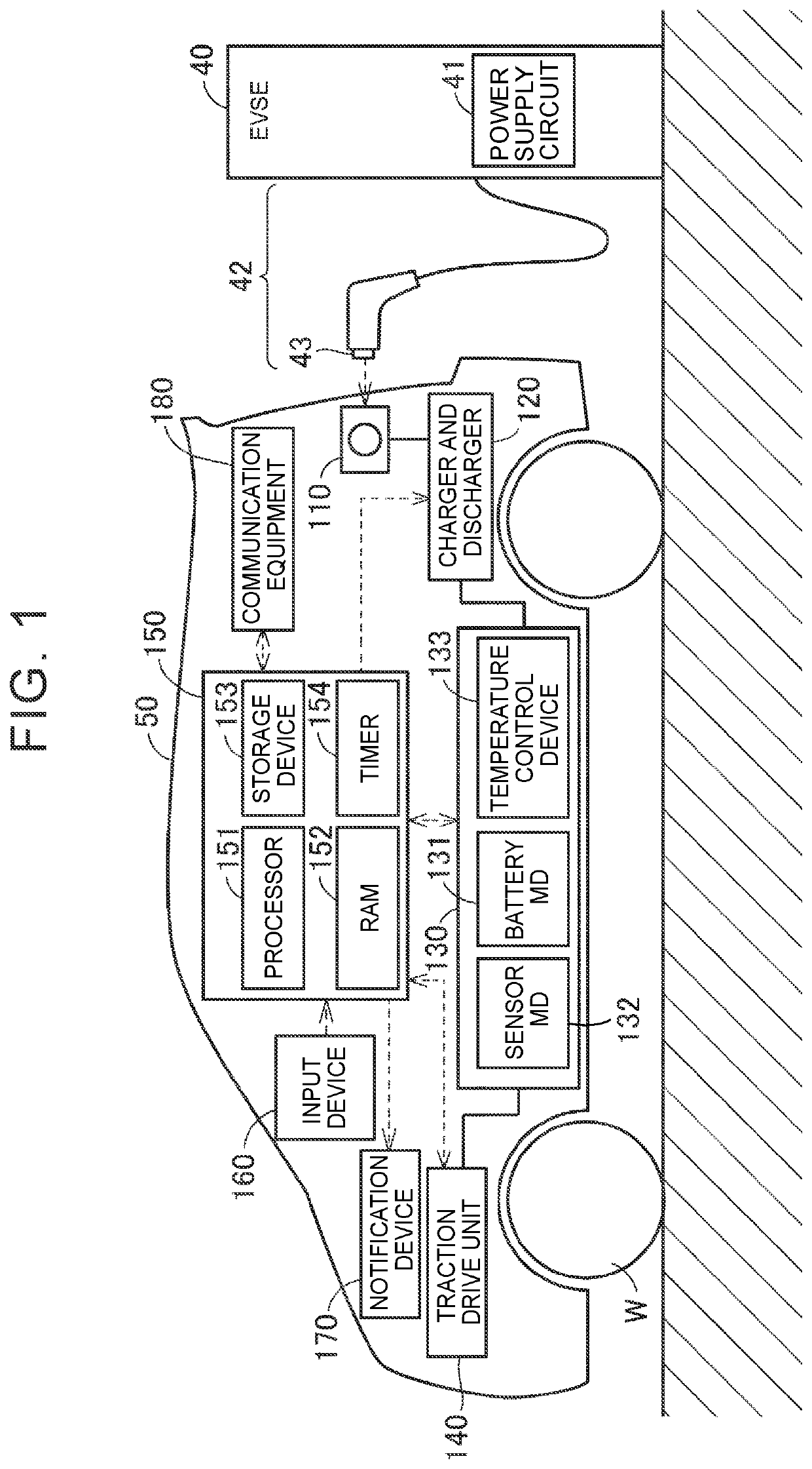
[0053]FIG. 1 shows a configuration of a vehicle equipped with a control system according to an embodiment of the present disclosure. Referring to FIG. 1, a vehicle 50 includes an inlet 110, a charger and discharger 120, a battery pack 130, a traction drive unit 140, an electronic control unit (ECU) 150, an input device 160, a notification device 170, communication equipment 180, and drive wheels W. The battery pack 130 includes a battery module (hereinafter referred to as “battery MD”) 131, a sensor module (hereinafter referred to as “sensor MD”) 132, and a temperature control device 133.

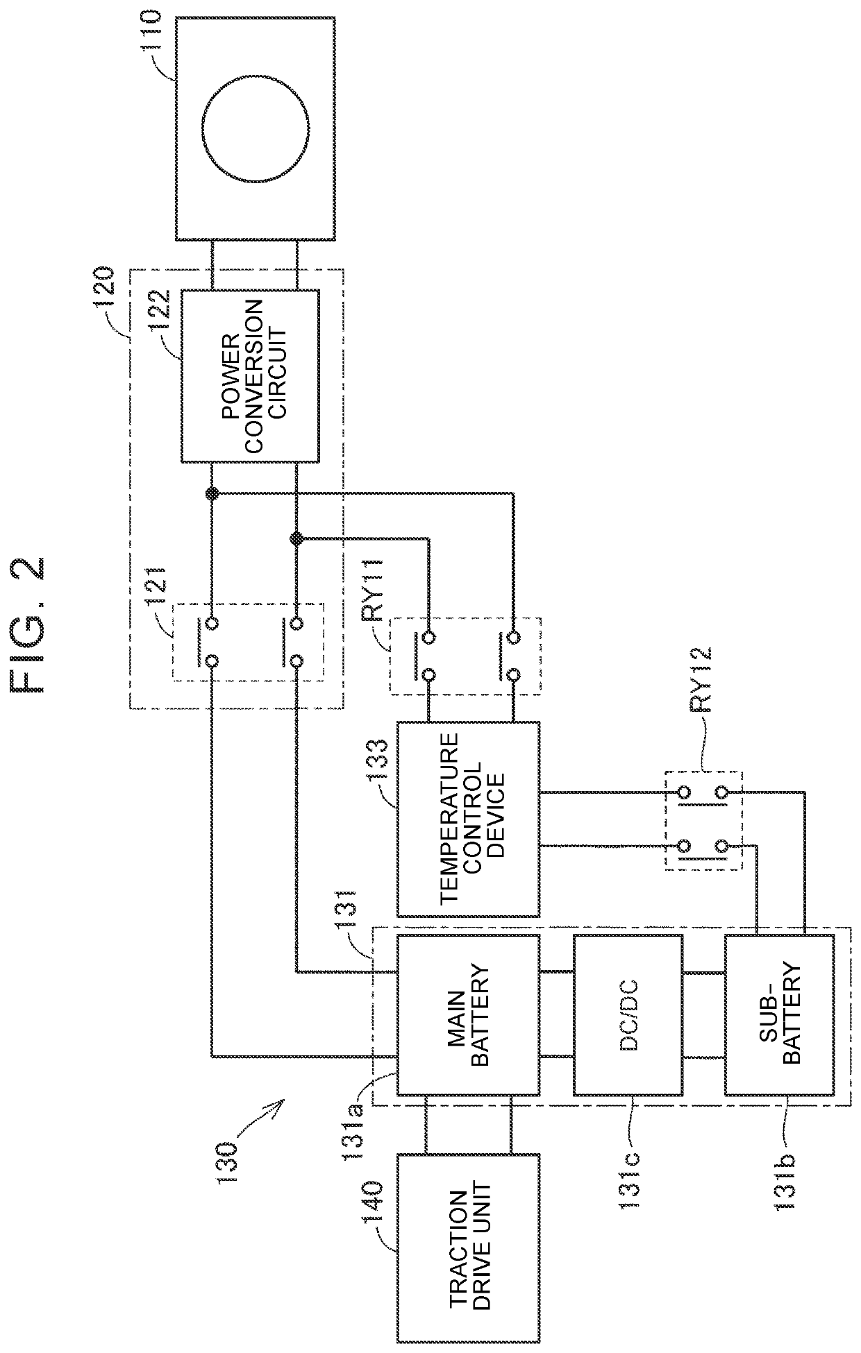
[0054]FIG. 2 shows a detailed configuration of the charger and discharger 120 and the battery pack 130. Referring to FIG. 2 together with FIG. 1, the b...


PUM


Abstract

A control system is configured to control a power adjustment resource including an energy storage device configured to electrically connect to a power network, and a temperature control device configured to perform temperature control of the energy storage device. The control system includes: a first control device configured to control charging and discharging of the energy storage device; a second control device configured to control the temperature control device; and a third control device. The second control device is configured to select either external power or stored power and drives the temperature control device using the selected power. The third control device is configured to determine whether to permit power supply from the power network to the power adjustment resource based on supply and demand information of the power network, and switch between permission and prohibition of the power supply.

Description

CROSS-REFERENCE TO RELATED APPLICATION[0001]This application claims priority to Japanese Patent Application No. 2021-040357 filed on Mar. 12, 2021, incorporated herein by reference in its entirety.BACKGROUND1. Technical Field[0002]The present disclosure relates to control systems and energy management methods.2. Description of Related Art[0003]Japanese Unexamined Patent Application Publication No. 2019-122174 (JP 2019-122174 A) discloses a technique for providing an ancillary service using an energy storage device. Charge and discharge capability of an energy storage device (particularly, the power that can be output from the energy storage device and the power that can be input to the energy storage device) varies depending on the temperature of the energy storage device. Accordingly, when providing an ancillary service, a control system described in JP 2019-122174 A drives a temperature control device (heater, heat pump, cooling fan, etc.) to perform temperature control of the ene...

Claims


Application Information

Patent Timeline
IPC IPC(8): B60L53/63B60L58/24B60L53/20B60L53/66B60L53/68H02J7/00H02J13/00H02J3/32
CPCB60L53/63B60L58/24B60L53/20B60L53/66B60L53/68H02J7/0071H02J13/00006H02J3/322H02J7/0048H02J2300/24H02J2300/28B60L58/10H02J1/14H02J2310/48H02J13/00032
Inventor TSUCHIYA, YOSHIYUKI
Owner TOYOTA JIDOSHA KK
Why Eureka
Try Eureka