Numerical controller capable of reducing machine load

a controller and machine technology, applied in the field of numerical controllers, can solve the problems of reducing the life of the machine, difficult to achieve the adjustment on the spot, and the cycle time finally required by such a dynamic change of feed speed, so as to reduce the impact of the machine, reduce the aging degradation of the machine, and restrict the machining time

Active Publication Date: 2018-02-27
FANUC LTD
View PDF5 Cites 2 Cited by
  • Summary
  • Abstract
  • Description
  • Claims
  • Application Information

AI Technical Summary

Benefits of technology

[0009]Accordingly, the object of the present invention is to provide a numerical controller capable of minimizing an impact produced in a machine while restricting the machining time within a tact time.
[0015]According to the present invention, there can be provided a numerical controller capable of minimizing an impact produced in a machine while restricting the machining time within a tact time, whereby aging degradation of the machine can be suppressed, and hence, the equipment cost can be reduced.

Problems solved by technology

The higher the acceleration, however, the greater the mechanical shock is, resulting in a reduction in the life of the machine.
Conventionally, manual adjustment is needed to set a large acceleration / deceleration time constant in order to reduce the gradient of acceleration and deceleration, and it is difficult to achieve the adjustment on the spot.
However, this technique is designed to adjust the acceleration / deceleration time constant to achieve energy conservation, based on the correlation between the cycle time and the sum total of motor load currents and power consumptions of peripheral equipment, not considering suppression of vibration and shock on a machine.
According to this technique, however, no consideration is given to cycle times finally required by such a dynamic change of the feed speed.

Method used


Image

  • Numerical controller capable of reducing machine load
  • Numerical controller capable of reducing machine load
  • Numerical controller capable of reducing machine load

Examples


Embodiment Construction

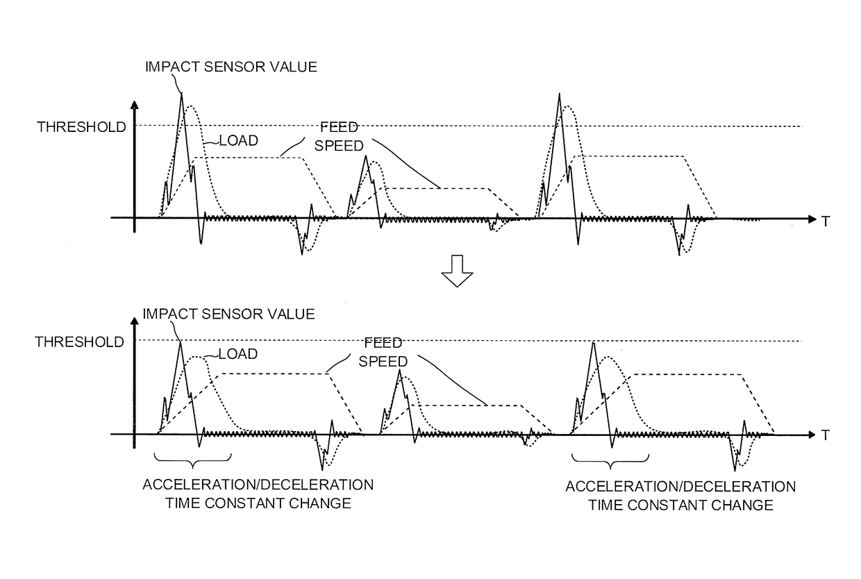
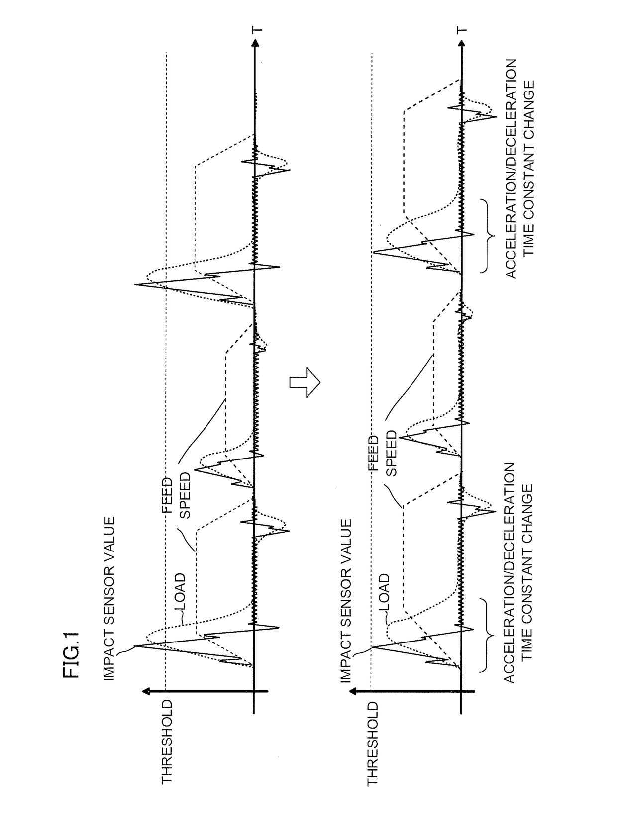
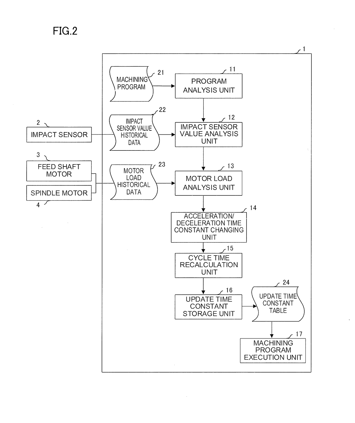
[0026]According to the present invention, a test run is performed with a tact time of an entire machining program given in advance, and the loaded conditions of a feed shaft and a spindle for the entire machining program and a value in an impact sensor attached to a machine are recorded as historical data. The impact sensor mentioned here is a sensor that can detect the acceleration of a moving object.

[0027]If the cycle time is within the previously given tact time and can be extended without a problem, a portion where the value in the impact sensor is large (e.g., a portion where the value exceeds a threshold) is detected, as shown in FIG. 1, and the acceleration or deceleration time (necessary time for acceleration or deceleration) for the detected point is changed so as to increase within such a range that the cycle time does not exceeds the tact time. Change information on a time constant of the acceleration and deceleration may be recorded on an internal memory or otherwise emb...


PUM


Abstract

A numerical controller obtains a maximum value of an impact produced in a machine during execution of a machining program, identifies an acceleration / deceleration time constant at a point where the maximum value of the impact is generated, based on command data, if the obtained value exceeds a threshold, changes the identified time constant, and recalculates a cycle time of the machining program based on the changed time constant. If the cycle time is within a preset tact time, the changed time constant is stored in advance in association with an identified command block so that it is referred to during the execution of the machining program.

Description

RELATED APPLICATION DATA[0001]This application claims priority under 35 U.S.C. § 119 and / or § 365 to Japanese Application No. 2015-029824 filed Feb. 18, 2015, the entire contents is incorporated herein by reference.BACKGROUND OF THE INVENTION[0002]Field of the Invention[0003]The present invention relates to a numerical controller capable of reducing machine load.[0004]Description of the Related Art[0005]Normally, in adjusting the acceleration and deceleration of a feed shaft and a spindle of a machine, the time required for the acceleration and deceleration is set as short as possible. By doing this, the cycle time of an entire machining program can be minimized. The higher the acceleration, however, the greater the mechanical shock is, resulting in a reduction in the life of the machine. A technique disclosed in Japanese Patent Application Laid-Open No. 2010-250697 is known as a conventional technique for automatically adjusting acceleration and deceleration.[0006]As shown in FIG. ...

Claims


Application Information

Patent Timeline
Patent Type & Authority Patents(United States)
IPC IPC(8): G06F19/00G05B19/406
CPCG05B19/406G05B2219/39086G05B19/19G05B2219/32184
Inventor NODA, KOUICHIENDO, TAKAHIKO
Owner FANUC LTD
Why Eureka
Try Eureka