Electric linear motion actuator

a technology of linear motion and actuator, which is applied in the direction of gearing, magnetic circuit rotating parts, and magnetic circuit shape/form/construction, etc., can solve the problems of increasing response, deteriorating responsiveness and control accuracy, and extremely limited installation space in the vehicle, etc., to achieve high torque, space saving, and low cost.

Active Publication Date: 2019-03-28
NTN CORP
View PDF0 Cites 0 Cited by
  • Summary
  • Abstract
  • Description
  • Claims
  • Application Information

AI Technical Summary

Benefits of technology

[0037]In this case, the rotor can be formed as a so-called double rotor type which is provided with two magnetic field mechanisms respectively arranged on both surfaces, opposite in the axial direction, of the excitation mechanism. One of the magnetic field mechanisms is fixed, to the rotation input-output shaft, at the axial position corresponding to a portion between the axial end surface of the housing and the torque generating surface of the excitation mechanism facing the axial end surface. The excitation mechanism and the axial end surface of the housing are coaxially coupled via the positioning structure. As the positioning structure, the configuration using, for example, spigot fitting is inexpensive and simple, and thus is suitable.
[0038]An electric brake device according to the present invention includes either of the aforementioned electric linear motion actuators, a brake rotor, and a friction member configured to generate a braking force by coming into contact with the brake rotor. According to this configuration, space saving and high torque can be achieved in the electric linear motion actuator. Thus, the electric brake device can be installed in a vehicle in which an installation space for the electric linear motion actuator is extremely limited. Consequently, the versatility of the electric brake device can be enhanced so that the electric brake device can be installed in various vehicles.

Problems solved by technology

In general, in such an electric brake device using an electric linear motion actuator such as that described in Patent Document 1 or 2, an installation space therefor in a vehicle is extremely limited.
For example, in a structure in which an electric motor is arranged on the outer circumference of an actuator as in Patent Document 1, the rotor diameter of the electric motor is increased, and thus, the moment of inertia is increased so that the responsiveness and the control accuracy may be deteriorated.
Meanwhile, since kinetic energy required to rotate a rotor is proportional to the moment of inertia, instantaneous maximum power consumption to implement a high-speed response may be increased, and thus the cost of a power supply device for supplying power thereto may be increased.
In this case, since an electric motor is close to a heat source, the durability may become a problem.
This may complicate the structure.
This may generate a certain amount of dead space in a gap therebetween.
Further, a coupling mechanism such as a parallel gear is needed between the electric motor and the linear motion actuator, irrespective of required specifications, resulting in a possible increase in the cost.
In addition, respective support structures are needed for the electric motor and the linear motion actuator, so that problems relating to space and cost may arise.

Method used


Image

  • Electric linear motion actuator
  • Electric linear motion actuator
  • Electric linear motion actuator

Examples


Embodiment Construction

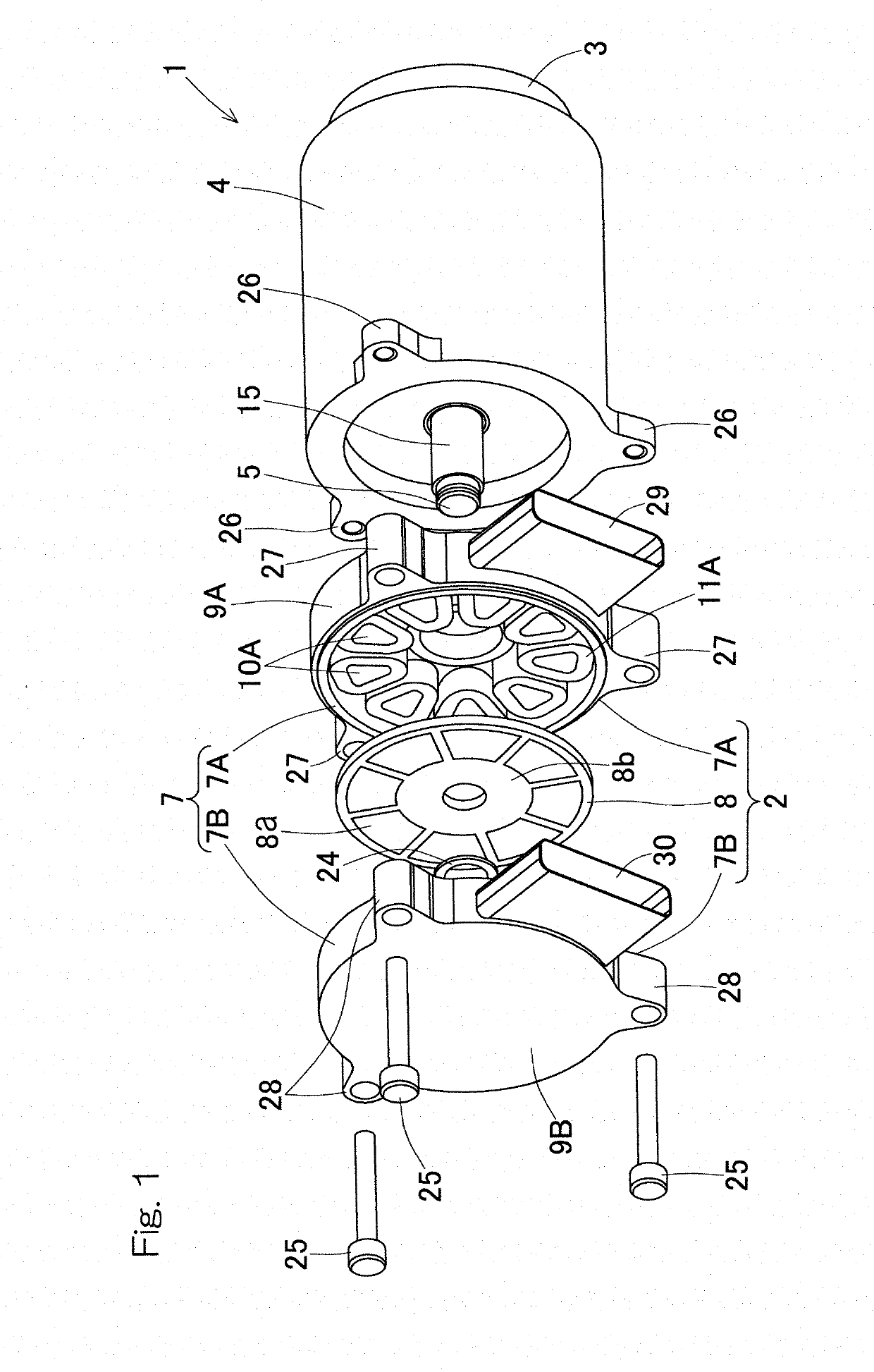
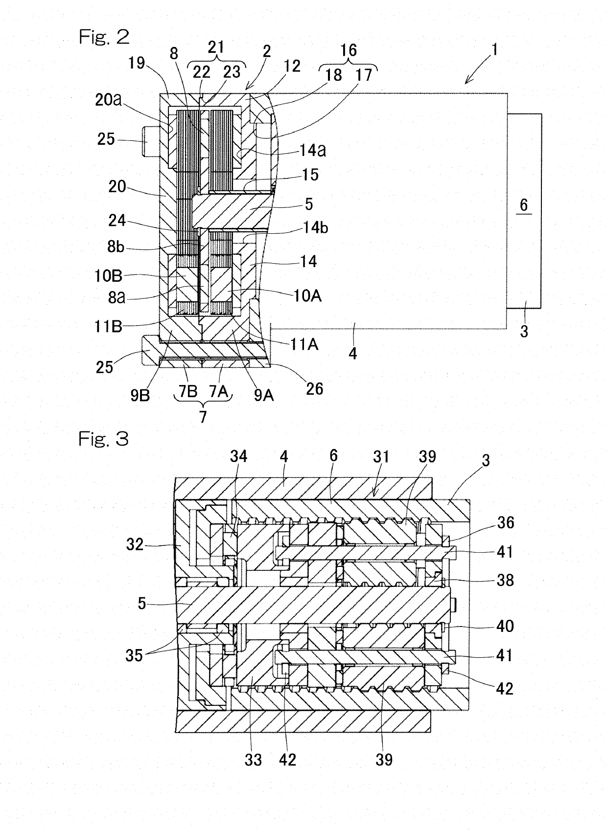
[0047]An electric linear motion actuator according to an embodiment of the present application will be described with reference to FIG. 1 to FIG. 3. The electric linear motion actuator is installed in an electric brake device (described later) mounted in a vehicle, for example. As illustrated in FIG. 1 and FIG. 2, the electric linear motion actuator 1 is an actuator in which an electric motor 2 and a linear motion mechanism 3 are connected in series in the axial direction. The electric linear motion actuator 1 includes the electric motor 2, the linear motion mechanism 3, and a housing 4. The electric motor 2 of the present embodiment is a double stator type axial gap motor. The linear motion mechanism 3 has a linear motion part 6, and converts rotary motion of the electric motor 2 to linear motion of the linear motion part 6 via a rotation input-output shaft 5 (described later). The housing 4 holds the linear motion mechanism 3. Illustration of some components such as wiring are omi...


PUM


Abstract

The electric linear motion actuator includes an electric motor, a linear motion mechanism configured to convert rotary motion of the electric motor to linear motion of a linear motion part via a rotation input-output shaft, and a housing holding the linear motion mechanism. The electric motor includes a stator and a rotor which are arranged such that the directions of magnetic poles that generate interlinkage flux contributing to a motor torque are parallel with a rotation axis of the electric motor. The stator is arranged so as to be coupled with an axial end surface of the housing. The rotor is arranged so as to have a space, in the axial direction, from the torque generating surface of the stator, and the rotor is fixed to the rotation input-output shaft of the linear motion mechanism.

Description

CROSS REFERENCE TO THE RELATED APPLICATION[0001]This application is a continuation application, under 35 U.S.C. § 111(a), of international application No. PCT / JP2017 / 017790, filed May 11, 2017, which is based on and claims Convention priority to Japanese patent application No. 2016-100177, filed May 19, 2016, the entire disclosure of which is herein incorporated by reference as a part of this application.BACKGROUND OF THE INVENTIONField of the Invention[0002]The present invention relates to an electric linear motion actuator applicable to an electric brake device, for example.Description of Related Art[0003]As an electric actuator and an electric motor, the following documents suggest:[0004]1. an electric disk brake device in which, on the outer circumference of a linear motion part, an electric motor is arranged coaxially with the linear motion part (Patent Document 1);[0005]2. an electric brake device in which an electric motor is arranged on an axis different from the rotation ax...

Claims


Application Information

Patent Timeline
Patent Type & Authority Applications(United States)
IPC IPC(8): H02K7/06H02K21/24H02K1/18H02K1/27H02K7/102F16D65/18B60T13/74
CPCH02K21/24H02K1/182B60T13/741H02K7/06F16D65/18H02K1/2793H02K7/1025F16H25/20F16D65/0006F16D2121/24F16D2125/40H02K1/2795B60T13/74
Inventor MASUDA, YUI
Owner NTN CORP
Why Eureka
Try Eureka