Valve and fluid tank for a fluid system, and a fluid system for a vehicle

a fluid system and valve body technology, applied in the direction of valve housings, electric propulsion mountings, machines/engines, etc., can solve the problems of severely limited installation space of valve body openings in the valve body, not necessarily the case, etc., to improve the utilization of the available installation space, the effect of clear width and simple manner

Active Publication Date: 2022-10-25
HELLA KG HUECK & CO
View PDF9 Cites 0 Cited by
  • Summary
  • Abstract
  • Description
  • Claims
  • Application Information

AI Technical Summary

Benefits of technology

[0007]Due to the inventive design of the valve for a fluid system of a vehicle, of the fluid tank for a fluid system of a vehicle, and of the fluid system for a vehicle, the aforementioned valve, the aforementioned fluid tank, and the aforementioned fluid system for a vehicle can be realized, on the one hand, in a particularly simple manner in terms of design and production technology. On the other hand, a flow-optimized shaping of the connecting pieces and the corresponding valve housing openings is realized as a result. This is because, in contrast to the prior art, the invention makes it possible for the connecting pieces and the valve housing openings corresponding thereto to also have cross sections with non-circular inner contours. The cross sections with substantially rectangular inner contours have a clear width that is greater in each case than that of a cross section with a circular inner contour. It is thus possible according to the invention to utilize particularly well the available installation space for the valve housing openings in the valve housing. The installation space for the valve housing openings in the valve housing is severely limited circumferentially, therefore, concentrically around the axis of rotation of the valve body. Accordingly, circular valve housing openings, for example, can only be enlarged to a limited extent in order to optimize the flow through the respective valve housing opening and the connecting piece corresponding thereto. This is where the present invention provides a remedy.
[0008]In principle, the valve of the invention can be freely selected within wide suitable limits in terms of type, functioning, material, and dimensioning.
[0009]The valve housing openings, which can be substantially rectangular in cross section, can be formed at least in part, preferably all valve housing openings, in each case such that a width, extending perpendicular to the axis of rotation, of said valve housing opening is formed to be smaller than a height, extending parallel to the axis of rotation, of said valve housing opening, preferably that the width extends along the valve housing opening arranged concentrically to the axis of rotation. This significantly improves the utilization of the available installation space for the valve housing openings. This applies in particular to the preferred embodiments of this refinement.
[0010]Corners of the valve housing openings, which can be substantially rectangular in cross section, can be formed rounded. In this way, the flow through the respective valve housing opening of the valve housing is additionally improved.
[0011]The free end of at least one connecting piece can be formed as a hose connection, preferably as a coupling part of a hose coupling, very preferably as a quick coupling part. This significantly simplifies the flow-conducting connection of the valve of the invention to the rest of the fluid system. Hoses and hose couplings are standard components that are available in a wide range of designs and can be used for a large number of different applications.
[0012]The connecting pieces can be jointly formed from a single first channel shell and from a single second channel shell, wherein the first channel shell is simultaneously formed as the valve housing which is connectable to the second channel shell for forming the connecting pieces. In this way, the valve of the invention can be realized in a particularly simple manner in terms of design and production technology. Further, this enables a centralization of the components of a fluid system for a vehicle. The first and / or the second channel shell can be formed in this case as a plastic injection molded part.

Problems solved by technology

This is not necessarily the case, however.
The installation space for the valve housing openings in the valve housing is severely limited circumferentially, therefore, concentrically around the axis of rotation of the valve body.

Method used


Image

  • Valve and fluid tank for a fluid system, and a fluid system for a vehicle
  • Valve and fluid tank for a fluid system, and a fluid system for a vehicle
  • Valve and fluid tank for a fluid system, and a fluid system for a vehicle

Examples


Embodiment Construction

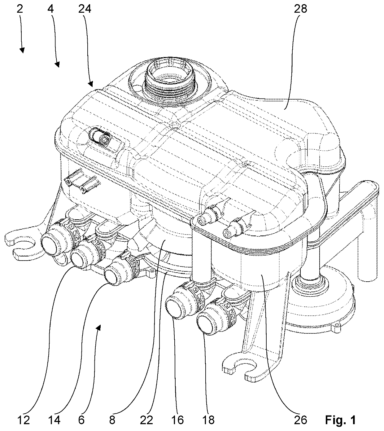
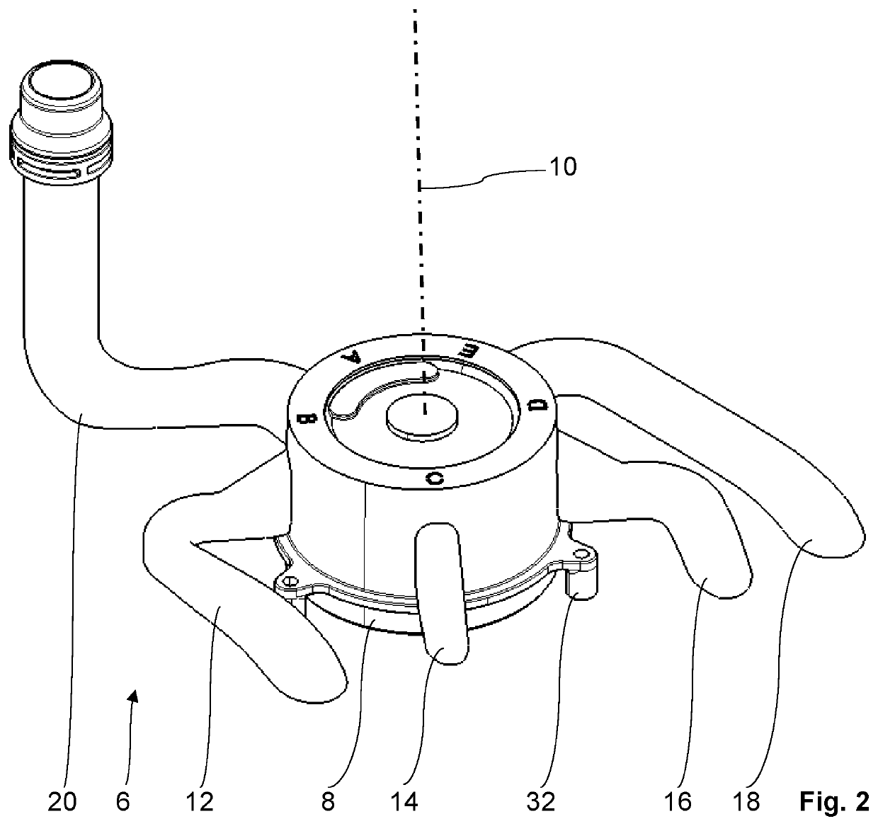
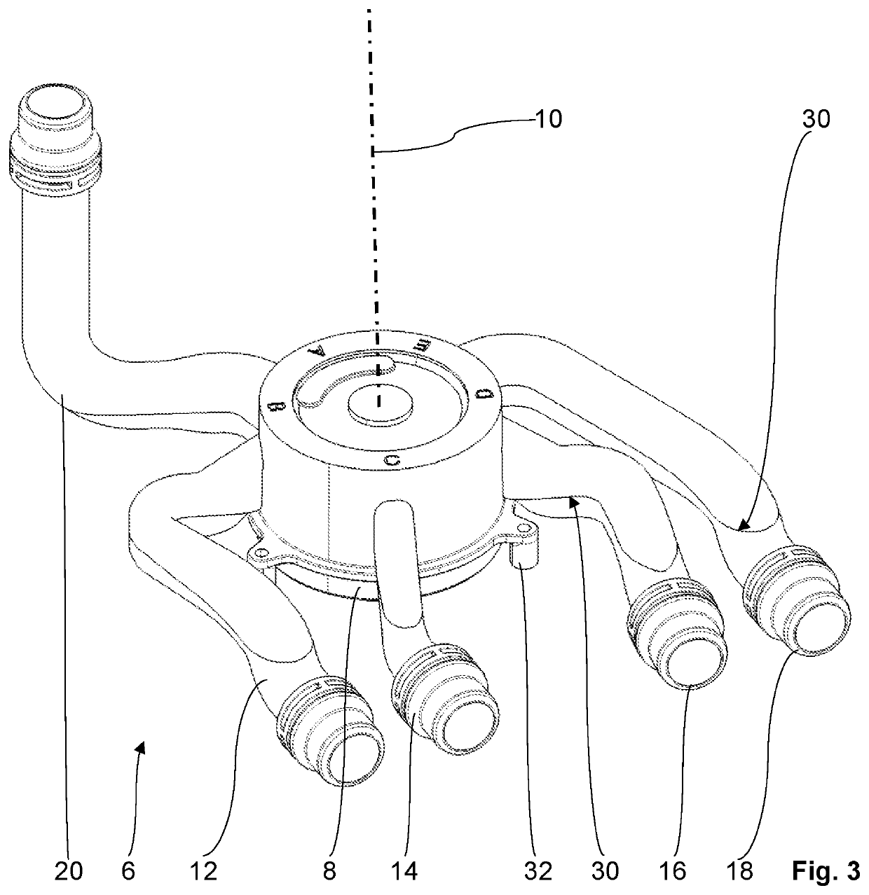
[0025]An exemplary embodiment of a vehicle with a fluid system of the invention is shown purely as an example in FIGS. 1 to 4.

[0026]The vehicle is designed here as a motor vehicle, namely, a pure electric vehicle, and is not shown in more detail.

[0027]In the present exemplary embodiment, fluid system 2 for the vehicle is formed as a coolant system for cooling the traction battery and the drive motor together with the power electronics corresponding thereto, and for cooling a refrigerant circuit for air conditioning an interior of the vehicle. The traction battery, the drive motor with the corresponding power electronics, and the refrigerant circuit of the vehicle are also not shown in detail here and are designed, for example, in a manner known per se to the skilled artisan.

[0028]Fluid system 2, formed as a coolant system, comprises a fluid tank 4, formed as a coolant tank, for storing a fluid (not shown) of the vehicle, said fluid formed as a coolant, a total of three fluid circuit...


PUM


Abstract

A valve for a fluid system of a vehicle having a valve housing with valve housing openings, a valve body arranged so as to be rotatable about an axis of rotation, a valve seal, a valve drive, and a plurality of connecting pieces corresponding to the valve housing openings. The connecting pieces have a circular flow passage area in cross section at a free end of the respective connecting piece, and the valve housing openings, corresponding to the connecting pieces, each have a substantially rectangular cross section. The respective valve housing opening is larger than the flow passage area at the free end of the corresponding connecting piece, and the flow passage areas of the connecting pieces widen in a diffuser-like manner from the free end of the respective connecting piece to the respective corresponding valve housing opening and merge in a stepless manner into the respective valve housing opening.

Description

[0001]This nonprovisional application claims priority under 35 U.S.C. § 119(a) to German Patent Application No. 10 2021 110 941.8, which was filed in Germany on Apr. 28, 2021, and which is herein incorporated by reference.BACKGROUND OF THE INVENTIONField of the Invention[0002]The present invention relates to a valve for a fluid system, to a fluid tank for a fluid system, and to a fluid system of a vehicle.Description of the Background Art[0003]Valves and fluid tanks of this kind for fluid systems and fluid systems for vehicles are already known from the state of the art in numerous design variants. The known valves for fluid systems of vehicles comprise a valve housing with a plurality of valve housing openings, a valve body arranged in the valve housing so as to be rotatable about an axis of rotation and having at least one flow-conducting connecting channel for the flow-conducting connection of at least two valve housing openings of the plurality of valve housing openings, a valve...

Claims


Application Information

Patent Timeline
Patent Type & Authority Patents(United States)
IPC IPC(8): F01P7/14F01P11/04F01P11/02
CPCF01P7/14F01P11/029F01P11/04F01P2007/146F16K11/085F16K27/065B60H1/00485F16K11/0853B60K11/02B60Y2200/90B60K2001/003Y02A50/20
Inventor BEWERMEYER, FRANKGROTHE, BENJAMINNIESS, DOMINIKTIEMEYER, SEBASTIANFISCHER, FINN MALTE
Owner HELLA KG HUECK & CO
Why Eureka
Try Eureka