

Instrumentation control system
- Summary
- Abstract
- Description
- Claims
- Application Information
AI Technical Summary
Benefits of technology
Problems solved by technology
Method used
Image

Examples
first embodiment
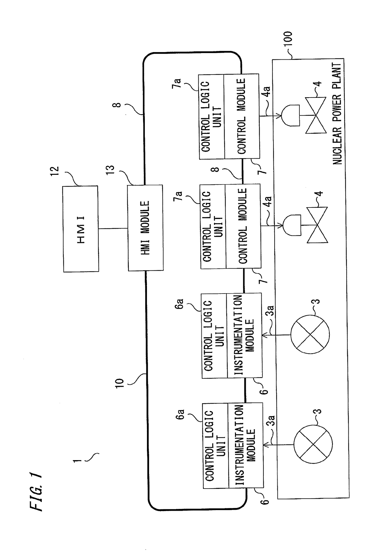
[0018]FIG. 1 is a configuration diagram showing an instrumentation control system according to the first embodiment of the present invention. In the first embodiment, an example in which the instrumentation control system according to the present invention is applied to a nuclear power plant, is shown. However, without limitation to a nuclear power plant, the instrumentation control system of the present invention is widely applicable also to other plants such as an industrial plant.
[0019]The instrumentation control system 1 of the first embodiment includes, in a plant: various sensors 3 such as a thermometer, a pressure meter, a level meter, and a flowmeter; and actuators 4 such as a control valve, a pump, a motor, and a cylinder. Here, the above various sensors 3 and various actuators 4 are collectively referred to as field devices.
[0020]In the first embodiment, instrumentation modules 6 are individually provided adjacently to the various sensors 3, and control modules 7 are indiv...
second embodiment
[0031]FIG. 4 is a configuration diagram showing an instrumentation control system 1 according to the second embodiment of the present invention. The components that correspond to or are the same as those in the first embodiment shown in FIG. 1 are denoted by the same reference characters.
[0032]In the first embodiment shown in FIG. 1, connection among the instrumentation modules 6, the control modules 7, and the HMI module 13 is established by applying the wired communication cable 8 as a communication line for configuring the communication network 10. On the other hand, in the second embodiment, as shown in FIG. 4, as a communication network 10, a wireless router 14 as a master unit is provided, and the input / output modules 6, the input / output modules 7, and the HMI module 13 are each provided with a wireless communicator as a slave unit, to configure a wireless LAN.
[0033]As described above, in the second embodiment, it is possible to realize an instrumentation control system withou...
third embodiment
[0034]FIG. 5 is a configuration diagram showing an instrumentation control system 1 according to the third embodiment of the present invention. The components that correspond to or are the same as those in the first embodiment shown in FIG. 1 are denoted by the same reference characters.
[0035]In the first embodiment shown in FIG. 1, as a communication line for configuring the communication network 10, the wired communication cable 8 is used. In the third embodiment, as shown in FIG. 5, power can be supplied to the input / output modules 6, 7, using the communication cable 8.
[0036]That is, in the third embodiment, known power supply transmission technology such as PoE (Power over Ethernet), EtherCAT P, or USB PD (USB Power Delivery) is applied to the communication network 10, whereby so-called input / output bus power feeding is performed in which the communication cable 8 is caused to also serve to supply power to the instrumentation modules 6 and the control modules 7. Thus, the instal...
PUM
 Abstract
Description
Claims
Application Information