Electric dust collector

A technology of electric dust collection and dust collection electrode, which is applied in the direction of electrode structure, electrostatic separation, electrostatic effect separation, etc., can solve the problems of reduced dust collection efficiency of the device, difficulty in properly maintaining the load balance, poor dust collection ability and dust collection ability. , to achieve the effect of improving the dust collection capacity, suppressing the increase in the size of the device, and improving the dust collection efficiency

Active Publication Date: 2013-09-25
FURUKAWA IND MACHINERY SYST +1
View PDF8 Cites 11 Cited by
  • Summary
  • Abstract
  • Description
  • Claims
  • Application Information

AI Technical Summary

Problems solved by technology

[0011] In addition, as described in Patent Document 1, in order to effectively collect dust from the gas with a low concentration of dust, the discharge electrode and the dust collection electrode of the first dust collection part arranged on the upstream side In the case where the discharge electrode and the dust collecting electrode are arranged densely in the second dust collecting part on the downstream side, the dust collecting ability of the dust collecting part on the upstream side is worse than that of the dust collecting part on the downstream side. When collecting dust from a gas with a high concentration of dust particles, it is difficult to properly maintain the load balance between the dust collection part on the upstream side and the dust collection part on the downstream side, and the dust collection efficiency of the device may decrease.

Method used


Image

  • Electric dust collector
  • Electric dust collector
  • Electric dust collector

Examples


Embodiment Construction

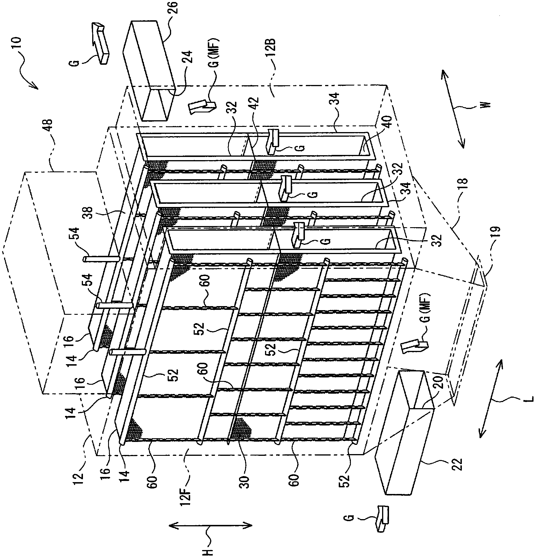
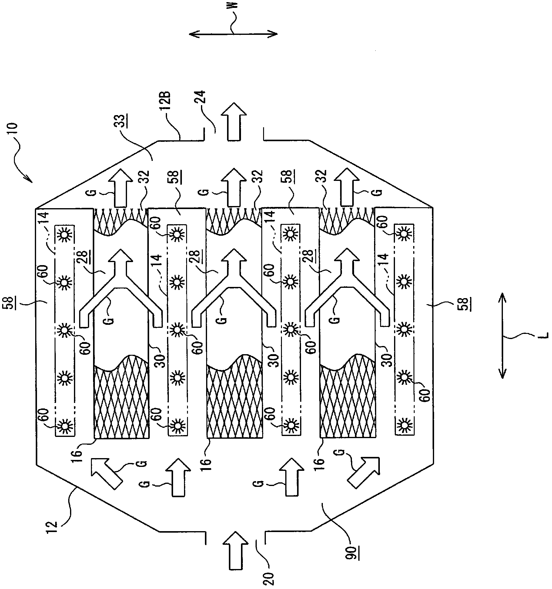
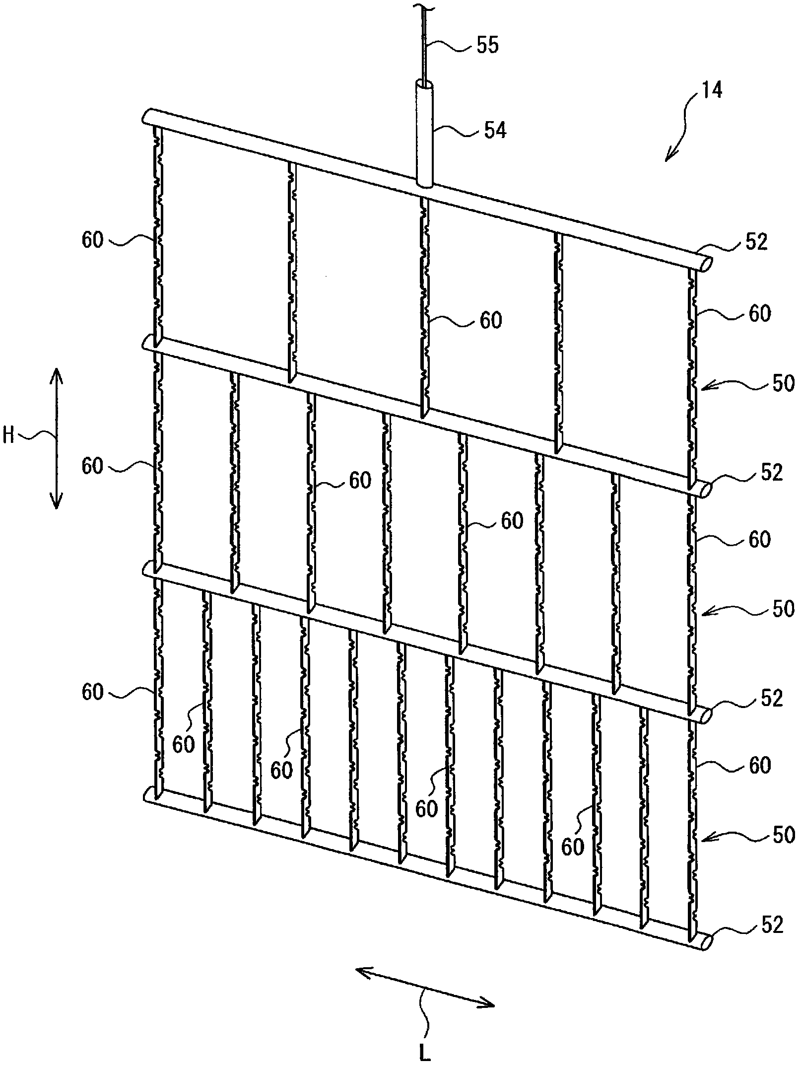
[0032] Next, an electric dust collector according to an embodiment of the present invention will be described with reference to the drawings.

[0033] exist figure 1 and figure 2 The configuration of the electric dust collector according to the embodiment of the present invention is shown in . This electric dust collector 10 includes: a hollow case 12 formed in a substantially rectangular parallelepiped shape; and a discharge electrode 14 and a dust collecting electrode 16 arranged inside the case 12 . like figure 1 As shown, a funnel-shaped hopper (hopper) 18 is provided on the bottom plate portion of the casing 12 so as to protrude downward. The bucket 18 is formed in the shape of a square tube whose cross-sectional area gradually decreases from the upper end side to the lower end side and penetrates in the height direction of the device (arrow H direction). Thereby, the dust-like objects collected inside the electric dust collector 10 can be stored in the lower part of...


PUM


Abstract

An object of the present invention is to provide an electric dust collector with its dust collecting performance being improved for collecting dust-like particles contained in a gas, whereas the increase in size thereof is being suppressed. An electric dust collector 10 distributes a gas G that has flown into a distribution chamber 90 to a plurality of charging flow paths 58 in a casing 12 thereof, causes the distributed gas to flow from insides of the charging flow paths 58 into internal flow paths 28 through mesh filters 30 that are formed as parts of the dust collecting electrodes 16 and that have large surface areas per unit volume. Then, the gas G is discharged to a central chamber 33 through internal outlets 32. Subsequently, the flow of the gas G is controlled to be discharged to the outside through a gas outlet 24.

Description

technical field [0001] The present invention relates to an electric dust collector for purifying gas containing dust-like bodies such as coal dust discharged from industrial equipment such as incinerators, melting furnaces, power generation boilers, and metal melting furnaces. Background technique [0002] In industrial devices such as incinerators, melting furnaces, power generation boilers, and metal melting furnaces, high-temperature exhaust gases containing dust-like objects such as coal dust (hereinafter referred to as "gas" .), and vent the gas to the outside of the device. After the gas discharged from industrial equipment is cooled to a certain temperature, it is sent to a filter type dust collector or an electric dust collector, and the dust is collected and removed by this dust collector. [0003] Comparing filter-type dust collectors with electric dust collectors, filter-type dust collectors using bag filters are generally better in terms of dust collection perfo...

Claims


Application Information

Patent Timeline
Patent Type & Authority Patents(China)
IPC IPC(8): B03C3/47B03C3/40B03C3/41
CPCB03C3/366B03C3/47B03C2201/10B03C3/09B03C2201/04B03C3/40B03C3/41
Inventor 名塚龙己杉并和启
Owner FURUKAWA IND MACHINERY SYST
Why Eureka
Try Eureka