Eureka AIR delivers breakthrough ideas for toughest innovation challenges, trusted by R&D personnel around the world.

Cyclone collector

a collector and cyclone technology, applied in the direction of filtration separation, cleaning filter means, separation processes, etc., can solve the problems of high risk of re-flying, high risk of clogging of filters, and pressure drop in the process, and achieve the effect of improving dust collection efficiency

Active Publication Date: 2010-06-08
LG ELECTRONICS INC
View PDF36 Cites 12 Cited by
  • Summary
  • Abstract
  • Description
  • Claims
  • Application Information

AI Technical Summary

Benefits of technology

[0018]An object of the present invention is to provide a cyclone collector which can improve suction power.
[0019]Another object of the present invention is to provide a cyclone collector which can improve dust collecting performance.
[0026]Accordingly, the present invention can improve dust collecting efficiency, and a suction power. The re-fly of the dust collected at the first cyclone can be prevented, effectively.

Problems solved by technology

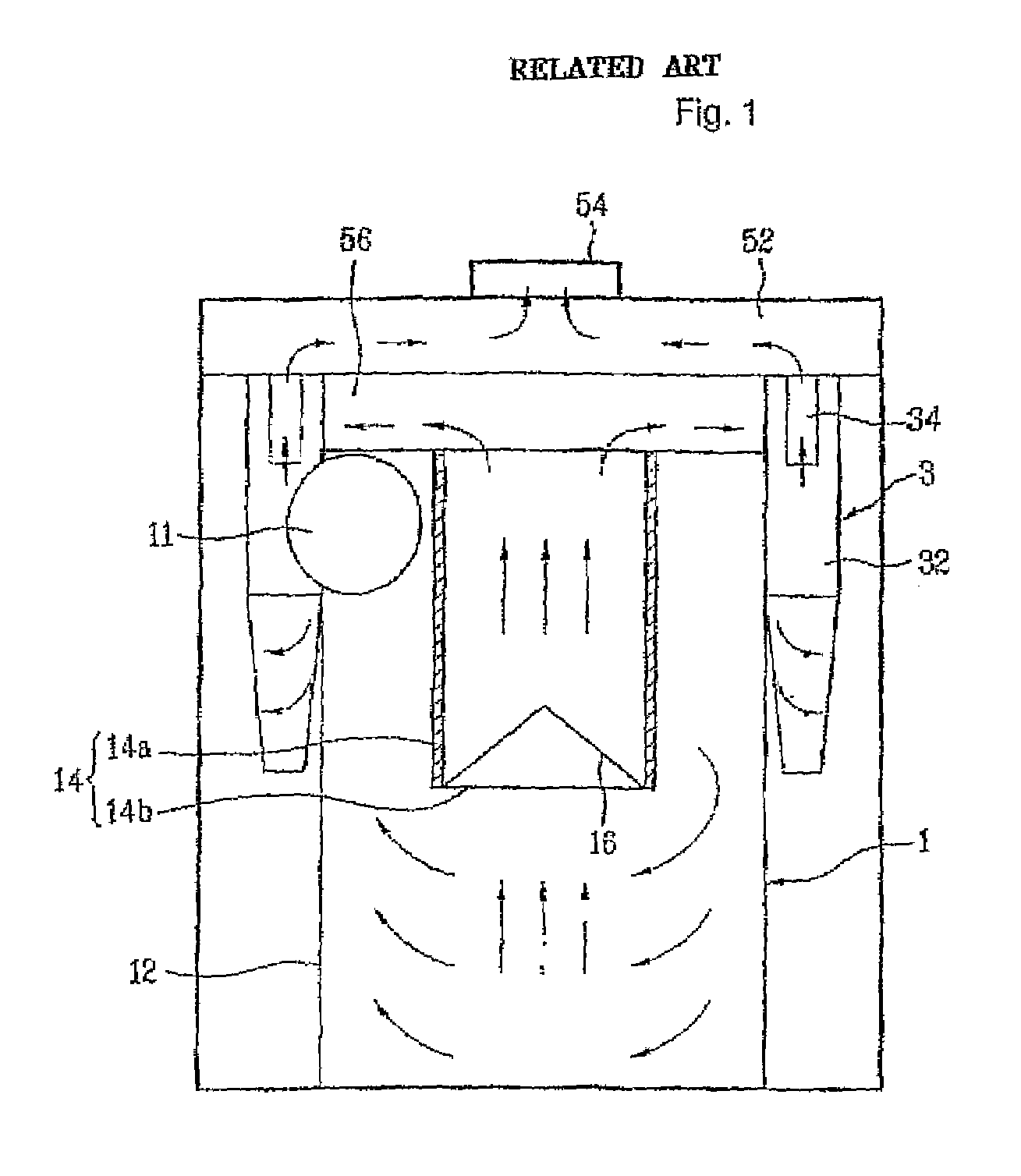
First, in the related art cyclone collector, air drawn through the inlet of the primary cyclone moves down to a lower portion of the inlet, and rises again, to escape from the cyclone. Though the dust is collected in this process, there is a pressure drop occurred in the process. That is, due to a great pressure loss, the related art cyclone collector is involved in drop of suction power.
Second, in the related art cyclone collector, the dust collected at the primary cyclone is liable to fly again, and move to the secondary cyclone. Moreover, since the air in the primary cyclone moves down to the lower portion of the inlet of the primary cyclone, the dust collected at the primary cyclone is highly vulnerable to re-fly.
Third, if a filter is mounted to the inlet of the primary cyclone of the related art multi-cyclone collector, the filter is liable to clog.

Method used


Image

  • Cyclone collector
  • Cyclone collector
  • Cyclone collector

Examples


Embodiment Construction

[0032]Reference will now be made in detail to the preferred embodiments of the present invention, examples of which are illustrated in the accompanying drawings. Wherever possible, the same reference numbers will be used throughout the drawings to refer to the same or like parts.

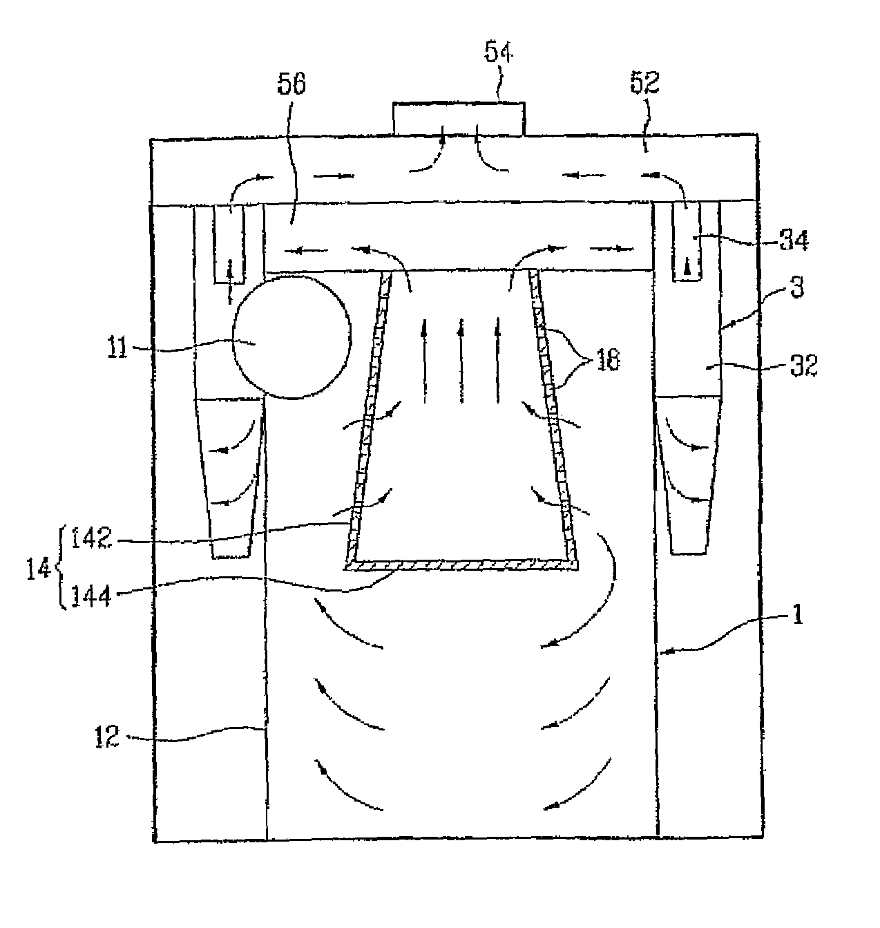
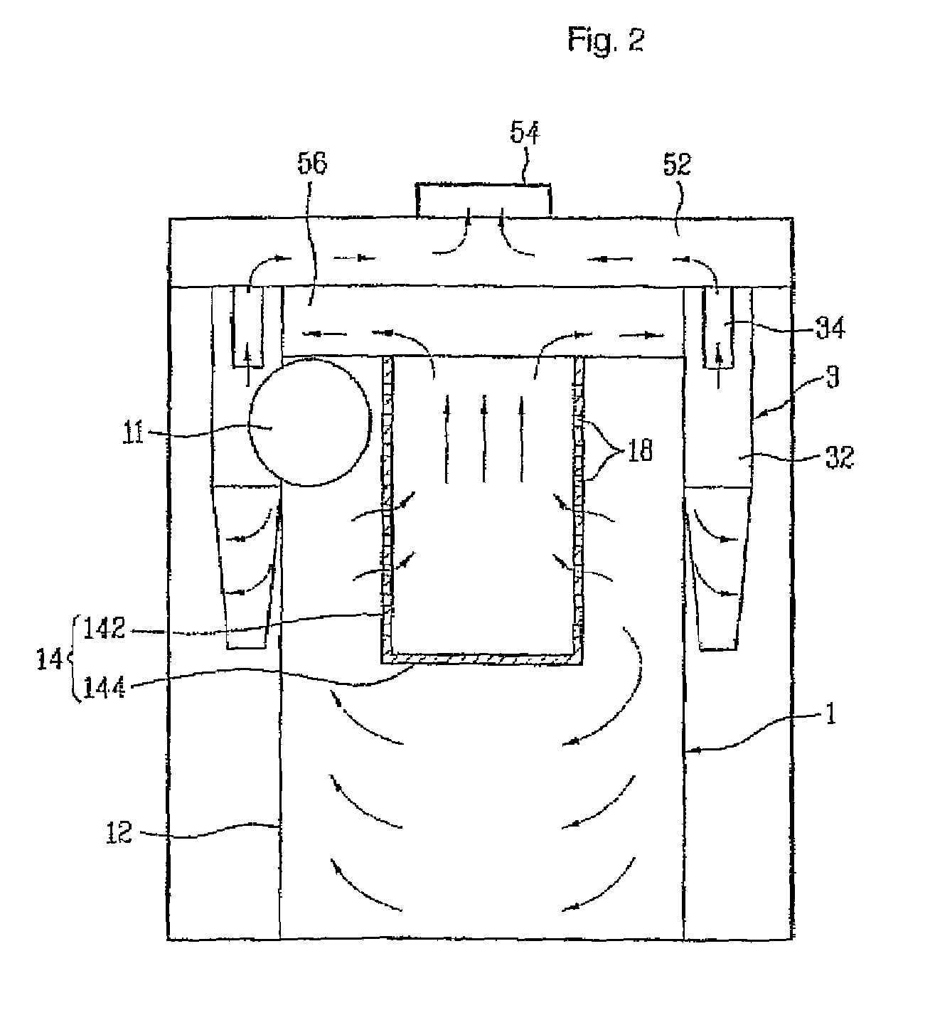
[0033]Referring to FIG. 2, alike the related art, the cyclone collector includes a primary cyclone 1, and a secondary cyclone 3 connected to the primary cyclone 1. However, in the present invention, a structure of the first inlet 14 of the primary cyclone 1 is different from the related art.

[0034]As described in the related art, until the present invention, in general it has been thought that the first outlet 14 of the first cyclone 1 is required to have an opened bottom, and no holes in an upper portion thereof. Ibis is because, in order to collect dust by the cyclone principle, air is required to swim downwardly along the inside wall of the body for separating the dust, and to move upward again substantial...


PUM

PropertyMeasurementUnit
diameteraaaaaaaaaa
slot shapeaaaaaaaaaa
areaaaaaaaaaaa

Abstract

A cyclone collector is provided that includes a body having an inlet that draws air therein, a cyclone provided inside of the body, and an outlet that discharges air from the body. The outlet includes a passage portion having a passage and a closed portion under the passage portion.

Description

TECHNICAL FIELD[0001]The present invention relates to cyclone collectors, and more particularly, to a dual cyclone collector having a plurality of cyclones connected to one another. Though application of the cyclone collector of the present invention is not limited to a vacuum cleaner, the cyclone collector of the present invention is particularly suitable to the vacuum cleaner.BACKGROUND ART[0002]The cyclone collector collects dust and dirt (hereafter called as dust, collectively) from air by using the principle of cyclone. The cyclone collector has wide applications, and applied to the vacuum cleaner as a domestic application.[0003]Currently, in order to improve dust collecting performance, the dual cyclone collector having a plurality of cyclone collectors connected to one another is used. That is, the dual cyclone collector is provided with an upstream cyclone for drawing air containing dust and the like (hereafter called as “dirty air”) and collecting comparatively large sized ...

Claims


Application Information

Patent Timeline
Patent Type & Authority Patents(United States)
IPC IPC(8): B01D45/00
CPCA47L9/1633A47L9/1641B04C5/13B04C5/26A47L9/1666Y10S55/03A47L9/16
Inventor LEE, SUNG HWAHYUN, KIE TAKSON, YOUNG BOKCHO, HYOUNG JOOJEONG, KYEONG SEON
Owner LG ELECTRONICS INC
Why Eureka
Eureka Blog
Learn More