Apparatus for filling containers having a magnetically operated closing cap

A container and conveying device technology, applied in the field of devices for filling containers, can solve problems such as inability to insert CIP caps

Active Publication Date: 2011-05-11
KRONES AG
View PDF3 Cites 9 Cited by
  • Summary
  • Abstract
  • Description
  • Claims
  • Application Information

AI Technical Summary

Problems solved by technology

This way, the insertion of the CIP caps cannot be performed during the aseptic phase of the filling machine

Method used


Image

  • Apparatus for filling containers having a magnetically operated closing cap
  • Apparatus for filling containers having a magnetically operated closing cap
  • Apparatus for filling containers having a magnetically operated closing cap

Examples


Embodiment Construction

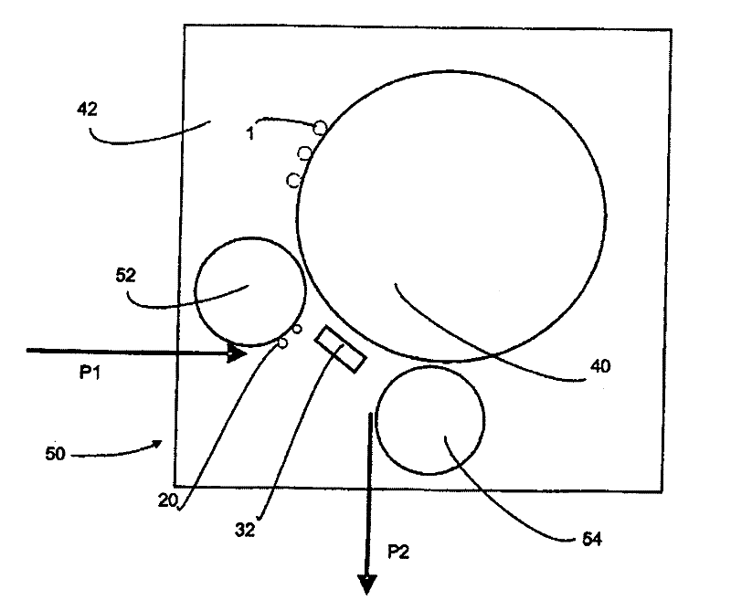
[0036] figure 1 A system 50 for filling containers 20 according to the invention is shown. The system 50 has a feeding device 52 which feeds the containers 20 to the transfer device 40 (cf. arrow P1 ). In this case, the feeding device 52 is a transfer star wheel or transfer wheel on which a plurality of gripping elements, such as tongs, are arranged for gripping the containers and transferring them to the transfer device 40 . A plurality of devices 1 for filling containers 20 with liquid are provided on a conveyor device 40 . In this case, storage means (not shown) are provided, from which liquid is filled into the container 10 .

[0037] Reference numeral 54 designates a removal device for removing the container from the combination device 50, as indicated by arrow P2. In this case, the transfer device 40 and the respective device 1 , supply device 52 and removal device 54 are arranged in a clean room 42 which is only diagrammatically shown. In this way, the filling of th...


PUM


Abstract

An apparatus (1) for filling containers with a liquid, having an outlet opening (2) via which the liquid can be filled into the container, having a liquid line (8) in order to feed the liquid to the outlet opening (2), and having a closing body (10) which can be moved between at least two positions in relation to the outlet opening, wherein the closing body (10) rests against the outlet opening (2) in a first position in order to close said outlet opening. According to the invention, the apparatus (1) has a first magnetic or magnetized element (12) which is arranged in a stationary manner in relation to the outlet opening (2) and interacts with a second magnetic or magnetized region (16) of the closing body (10) in order to move the closing body (10).

Description

technical field [0001] The invention relates to a device for filling containers. Background technique [0002] Filling plants usually have filling stations arranged on conveyors, which fill containers with liquids, in particular beverages. [0003] In this case, such filling in a sterile environment is required in various fields. The invention is therefore described in particular in connection with a so-called aseptic filling device, but it should be pointed out that the device according to the invention can also be used in other filling installations. [0004] It is known in the prior art to clean such filling devices with cleaning media during the CIP (Cleaning In Place) process for cleaning purposes. For this purpose, it is also known to close the outlet of the filling device with a CIP cap, in order to thus create a bypass between the outlet of the filling valve and the CIP circuit line. In this way, the filling unit can be cleaned and disinfected automatically. In t...

Claims


Application Information

Patent Timeline
Patent Type & Authority Applications(China)
IPC IPC(8): B67C3/00
CPCB67C3/004
Inventor 于尔根·泽尔纳霍尔格·穆勒奥拉夫·斯科特多夫
Owner KRONES AG
Why Eureka
Try Eureka