Connecting rod positioning mechanism

A technology of positioning mechanism and link mechanism, which is applied in the direction of workpiece clamping device, manufacturing tools, etc., can solve the problems of inability to take out, damage the accuracy of the shaft, and time-consuming positioning of the shaft, and achieve convenient operation and installation, fast and accurate positioning, and wide application range wide effect

Inactive Publication Date: 2011-05-18
JIANGSU LIUGONG MACHINERY +1
View PDF5 Cites 0 Cited by
  • Summary
  • Abstract
  • Description
  • Claims
  • Application Information

AI Technical Summary

Problems solved by technology

The problem of this positioning method is: when positioning the workpiece, it takes time to locate the shaft, and it is difficult to take out the shaft when the mold is lifted after assembly, and the accuracy of the shaft will be damaged if it is knocked out with a hammer; and for some blind hole structures or stepped hole structures , the shaft cannot pass through the workpiece for positioning or the shaft cannot be taken out when the mold is ejected after positioning with the shaft

Method used


Image

  • Connecting rod positioning mechanism
  • Connecting rod positioning mechanism
  • Connecting rod positioning mechanism

Examples


Embodiment Construction

[0013] Below in conjunction with accompanying drawing and specific embodiment, further illustrate the present invention, should be understood that these embodiments are only for illustrating the present invention and are not intended to limit the scope of the present invention, after having read the present invention, those skilled in the art will understand various aspects of the present invention Modifications in equivalent forms all fall within the scope defined by the appended claims of this application.

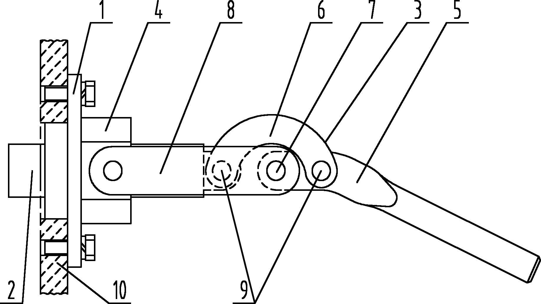
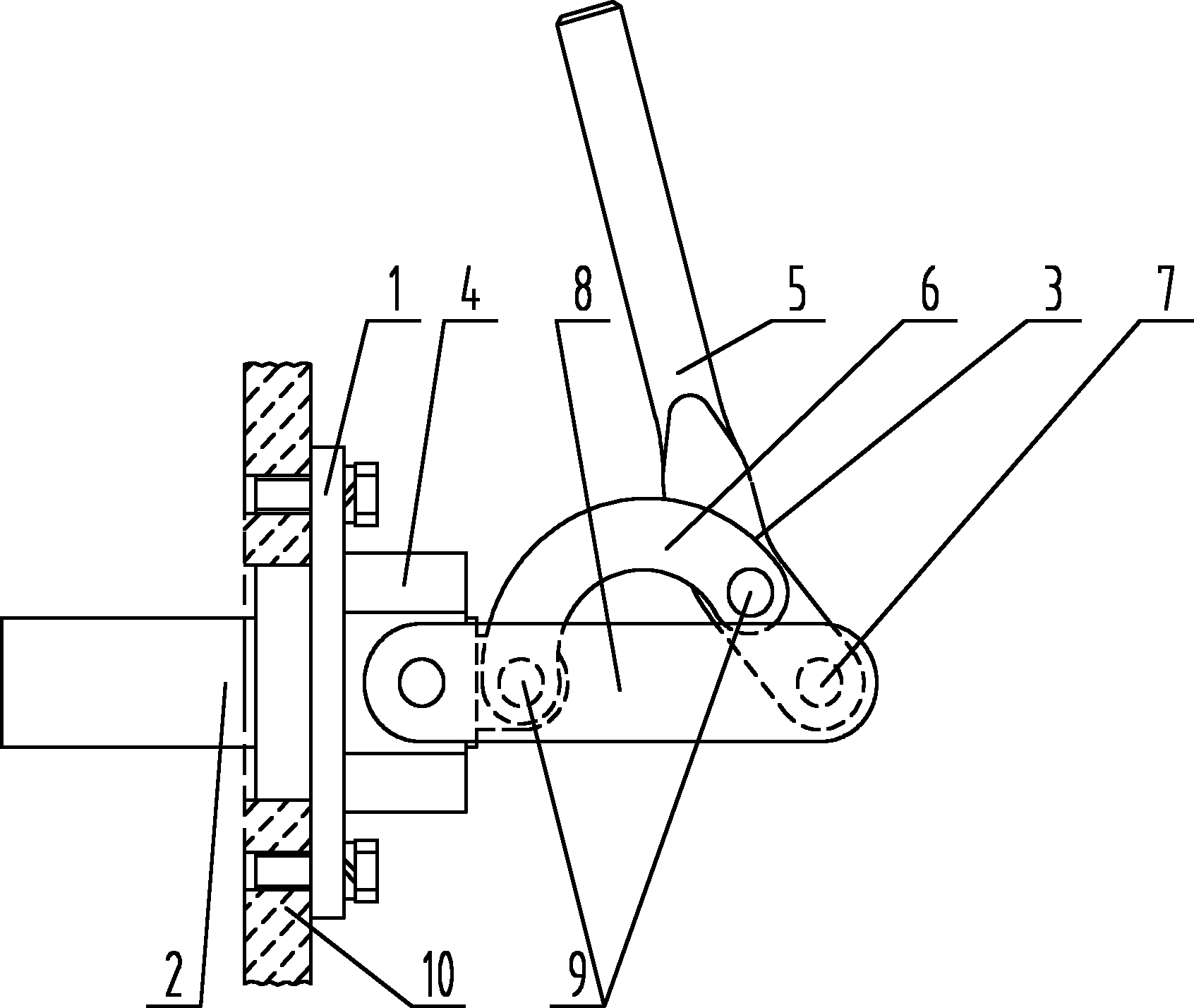
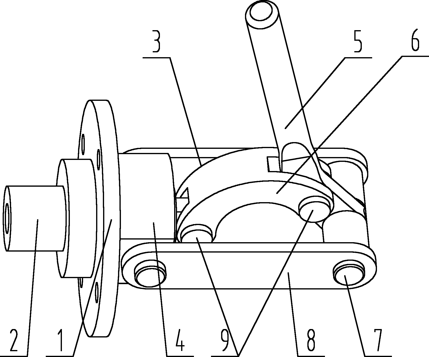
[0014] as attached Figures 1 to 3 As shown, a connecting rod positioning mechanism includes a mounting flange 1, a positioning shaft 2 and a connecting rod mechanism 3, and the connecting rod mechanism 3 includes a movable rod 5, a connecting rod 6 and a fixed shaft 7, and the connecting rod 6 has two The ends are respectively connected with one end of the positioning shaft 2 and the front end of the movable rod 5 with a pin 9, the top end of the movable rod 5 is connec...


PUM


Abstract

The invention discloses a connecting rod positioning mechanism. The mechanism comprises an assembly flange, a positioning shaft and a connecting rod mechanism, wherein the connecting rod mechanism comprises a movable rod, a connecting rod and a fixed shaft; two ends of the connecting rod are connected with one end of the positioning shaft and the front end of the movable rod by pins respectively; the top of the movable rod is connected through the fixed shaft; and the other end of the positioning shaft is opposite to the assembly flange. The connecting rod positioning mechanism has the advantages that front and back motion of the positioning shaft is implemented through a connecting rod transmission principle, the workpiece can be positioned accurately, shaft penetration and die stripping save power, and the operation and assembly are convenient. The positioning shaft can be detached and changed into different lengths and diameters according to actual requirement, so positioning of workpieces in different sizes can be implemented, and the application range is wide.

Description

technical field [0001] The invention relates to a positioning mechanism, in particular to a positioning mechanism for positioning a workpiece by using the transmission principle of a connecting rod. Background technique [0002] At present, when assembling workpieces such as steel structural parts, if some holes have size requirements, the holes need to be positioned. The usual method is to use the shaft to directly pass through the holes for positioning. The problem of this positioning method is: when positioning the workpiece, it takes time to locate the shaft, and it is difficult to take out the shaft when the mold is lifted after assembly, and the accuracy of the shaft will be damaged if it is knocked out with a hammer; and for some blind hole structures or stepped hole structures , the shaft cannot pass through the workpiece for positioning or the shaft cannot be taken out when the mold is ejected after positioning with the shaft. Contents of the invention [0003] P...

Claims


Application Information

Patent Timeline
Patent Type & Authority Applications(China)
IPC IPC(8): B25B11/00
Inventor 付红桂韦庆东李鹰赵京星
Owner JIANGSU LIUGONG MACHINERY
Why Eureka
Try Eureka