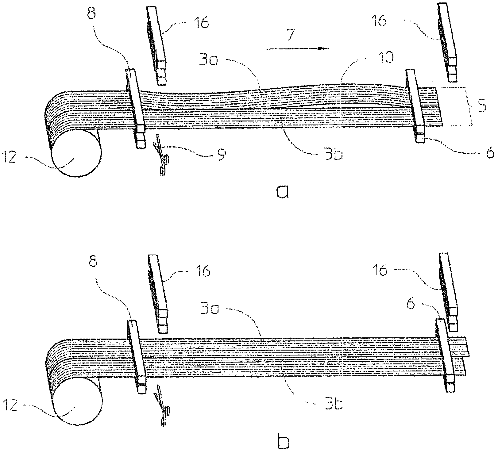
The method for producing a multi-axial wire structure in the form of an endless web, which is present in a transport device and moves itself with the transport device in its longitudinal direction, comprises broadening the fibers in an expanding process before displacing to unidirectional
fiber layers, where each
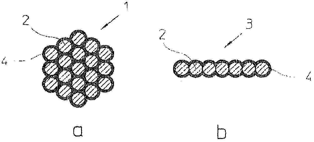
fiber is deformed to a strip, whose weight per unit area is highly 300 g / m 2>, and consecutively placing the unidirectional
fiber layers with their fibers in the form of individual segments (5) in alternating longitudinal direction by using a laying device. The method for producing a multi-axial wire structure in the form of an endless web, which is present in a transport device and moves itself with the transport device in its longitudinal direction, comprises broadening the fibers in an expanding process before displacing to unidirectional fiber
layers, where each fiber is deformed to a strip, whose weight per unit area is highly 300 g / m 2>, consecutively placing the unidirectional fiber layers with their fibers in the form of individual segments (5), which lie next to each other and consist of strips (3a, 3b), in alternating longitudinal direction by using a laying device, and temporarily fixing the unidirectional fiber layers at the transport device, where the longitudinal direction of the strips and the segments runs at an angle to the longitudinal direction of the resulting web-like wire structure. The
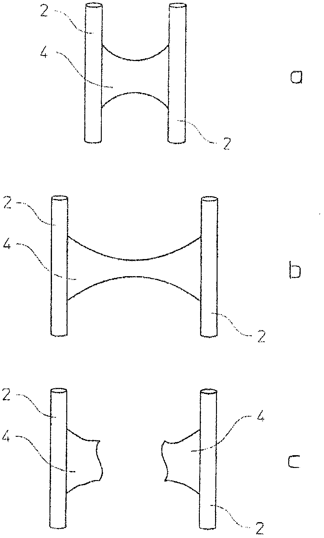
raw material of the unidirectional fiber layers are made of fibers consisting of filaments, where the fibers are provided with a size. A transverse coherence is given to the individual strips in a manner before joining to the segments. The strips that closely lie next to each other remain within the segment in an unbondable manner. The segments pass through the entire placing process in an unbondable condition of the strip in the segment. Coherence takes place between the strips and between the segments of the different unidirectional fiber layers by temporarily fixing at the transport device. During placing process, a gripper (6) of the laying device pulls the strips over the transport device transverse to the formation of the segments. An
equalization of different mechanical longitudinal stresses between the individual strips takes place in co-operation between the traction force of the gripper and the
restoring force of the strips. The adhesion effect of the size between the filaments of the fibers and / or strips is reduced by targeted effect on the fibers and / or strips. The already broadened fibers are provided as finished
intermediate product on disk coils, are removed by a wrap creel and are led to the gripper. A defined slippage of the strips is provided in the gripper and the ends of the segments turned away to the gripper are fixed into a clamping device (8) during the
equalization of the different mechanical longitudinal stresses of all strips. The already expanded fibers of the finished
intermediate product are provided on a common coil body of the disk coils, on which two already expanded fibers are winded next to each other. The broadening of the fibers takes place in a multi-axial
machine for the production of the multi-axial wire structure. The fibers removed by the wrap creel pass through a stationarily arranged spreading unit and are led into the gripper in the form of broadened strips. All strips are fixed into the gripper during the
equalization of the different mechanical longitudinal stresses and the
restoring force of the strip is introduced by the coils of the wrap creel and to the spreading unit. The wrap creel is controllably moved together with the spreading unit as a common
structural unit in a way, where the distance (L) is targetedly changed between the common
structural unit and the laying device. The movement of the
structural unit takes place at the strips in accordance with the requirement of the laying device varying in the
unit of time, so that the fibers pass through the spreading unit with
constant speed. The ends of the segments are fixed into the gripper for the equalization of the different mechanical longitudinal stresses of the individual strips. The segments are placed next to each other in a gas-free manner or are placed with an overlap or with a distance to each other. The targeted effects are mechanically, thermally or chemically carried out before, during or after the spreading. A cohesion medium is introduced before placing the segments on the fiber layers, is thermally activated after placing the segments and binds the fiber layers with one another. The adjacent strips are placed in a gas-free manner, placed with the overlap or placed spatially apart from each other. The transport device is a movable carrier, which is
textile layer of the wire structure. After placing all the unidirectional fiber layers, the multi-axial wire structure is supplied to a connecting
station, in which
all fiber layers are sutured with one another, knitted or calendared. The transport device consists of conveyor chains, which shortly and slightly diverge transverse to its transport direction before fixing the layers. Each of the fibers is separately spreaded. The fibers are guided in different levels during spreading, so that all fibers freely lie in a lateral manner. The fibers of the unidirectional fiber layers consist of discontinuous filaments. The material of the fibers is carbon,
ceramic, glass and / or aramide or consists of pre-products or intermediate products. The number of filaments is 12K. INDEPENDENT CLAIMS are included for: (1) an unidirectional
fiber layer; (2) a method for producing an unidirectional
fiber layer; (3) a coil body; (4) a multi-axial wire structure; and (5) composite part.

