Method for production of a multi-axial wire structure, unidirectional fiber layers and method for production thereof, multi-axial wire structure and composite part with a matrix

A unidirectional fiber, multiaxial technology, used in textiles and papermaking, conveying filamentous materials, coatings, etc., to solve problems such as violations, length differences and stress differences

Active Publication Date: 2011-05-18
KARL MAYER TECH TEXTILIEN GMBH
View PDF4 Cites 10 Cited by
  • Summary
  • Abstract
  • Description
  • Claims
  • Application Information

AI Technical Summary

Problems solved by technology

This violates the requirement for a smooth surface and can lead to length differences and stress differences between side-by-side strips

Method used


Image

  • Method for production of a multi-axial wire structure, unidirectional fiber layers and method for production thereof, multi-axial wire structure and composite part with a matrix
  • Method for production of a multi-axial wire structure, unidirectional fiber layers and method for production thereof, multi-axial wire structure and composite part with a matrix
  • Method for production of a multi-axial wire structure, unidirectional fiber layers and method for production thereof, multi-axial wire structure and composite part with a matrix

Examples


Embodiment Construction

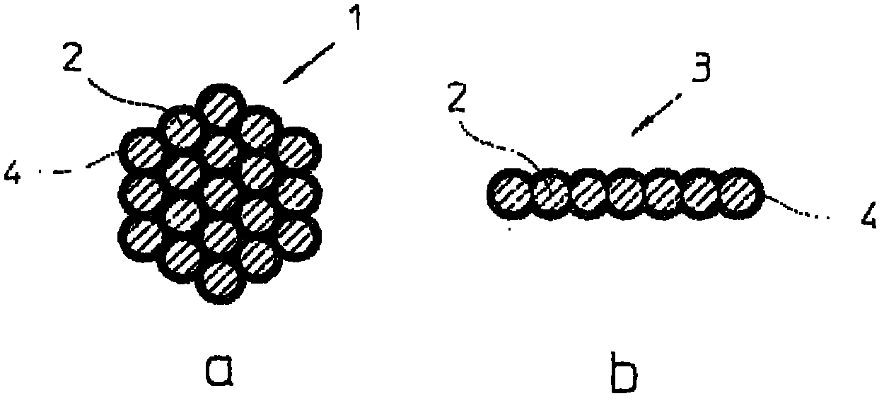
[0041] exist figure 1 A very schematic cross-sectional representation of an individual fiber 1 , which may be a carbon fiber, is shown in sub-figure a of . Fibers (often also called yarns, cables or monofilament cables) consist of a large number of monofilaments 2 . In the context of interest here, carbon fibers 1 with a K value of from 12 to 50 and greater, ie carbon fibers consisting of 12,000 to 50,000 individual filaments 2 and more, are possible. For economical reasons thinner fabrics of unidirectional yarns are produced, wherein fibers 1 are extracted as raw material according to the partial diagram a and widened in a spreading device. The fibers of the raw material do not necessarily have a polygonal or approximately circular cross-section as shown here. Common commercial forms also use fiber strips which already have an approximately rectangular flattened cross-section, but are still too thick for practical use and therefore likewise have to be widened.

[0042] De...


PUM

PropertyMeasurementUnit
widthaaaaaaaaaa
widthaaaaaaaaaa

Abstract

A known method from fiber engineering is improved in which fibers consisting of a large number of filaments are broadened out into bands (3a, 3b), placed side by side and pulled by a grasper (6) over a transport device in the form of segments (5) cut to size, and are secured thereon by means of an extending-clamping device (16). The direction of movement of the grasper (6) is denoted by reference number (7) and the required separating device by reference number (9). The novelty consists in that the bands (3a, 3b) of the segment (5) are combined and set to the side of the segment in an essentially non-bonded manner. A method is provided herein such that the measures for obtaining a transverse cohesion extending laterally across several bands (3a, 3b) are omitted. However, a transverse cohesion imprinted from the outside can extend across the filaments of a single band (3a, 3b). In this manner, the bands (3a, 3b) are set aside in a particularly uniform and smooth manner. When laid by means of the grasper (6), differences in length and tension between the single bands (3a, 3b) are compensated, which would be expressed, for example, as bulges (10). An additional, short tug on the already almost completely transported segment (5) is possible. The retention force for tightening can be applied by a braked supply coil of the starting material. The illustration 'a' denotes the state of the segment before the compensation movement, illustration 'b' denotes the state thereafter.

Description

technical field [0001] The invention relates to a method for producing a fabric of multiaxial yarns according to the preambles of claims 1 and 4 . Two methods of this type are disclosed from EP0972102B1. The multiaxial yarn fabric produced according to this method is firstly used to produce fiber-reinforced parts made of plastic, wherein the yarn fabric is embedded in a matrix made of plastic. [0002] The concept of "fiber" in this application is equivalent to cable, yarn, monofilament cable or roving. Individual fibers or yarns in each case are those that consist of a plurality of individual filaments and have an approximately circular or polygonal cross-section as raw material, but may also have a flattening in the form of a rectangle with rounded corners. (abgeflacht) cross section. If such fibers are required in the form of very thin layers, they are produced for cost reasons by widening or unrolling thicker cables, each consisting of 12000 (K value 12) or much more mo...

Claims


Application Information

Patent Timeline
Patent Type & Authority Applications(China)
IPC IPC(8): D04H3/02D04H3/04B29B15/14B65H57/16B65H59/32D04H3/004D04H3/009D04H3/10D04H3/11D04H3/12
CPCD04H3/004D02J1/18D04H3/10D04H3/009D04H3/11D04H3/04D04H3/02D04H3/12
Inventor 莱纳·索依斯
Owner KARL MAYER TECH TEXTILIEN GMBH
Why Eureka
Try Eureka