


Quick Research
Generate reliable direction feasibility study reports for your R&D in just a few steps.

Technical Q&A
Discover and master advanced knowledge NOW. Basics, ideas, possibilities, all at once.

Find Solutions
As an expert in R&D theories, this can generate solutions to your technical problems instantly.

Evaluate Feasibility
Analyze your overall solution with one click, know your potential R&D risks in advance.

Monitor Landscape
Get weekly tech updates, stay abreast of the latest tech innovations and key insights.
Image processing apparatus and image processing method
An image processing device and image technology, applied in image data processing, image enhancement, image analysis, etc., can solve problems such as unsuitable cameras
- Summary
- Abstract
- Description
- Claims
- Application Information
AI Technical Summary
Problems solved by technology
Method used
Image

Examples
no. 1 example
[0029]
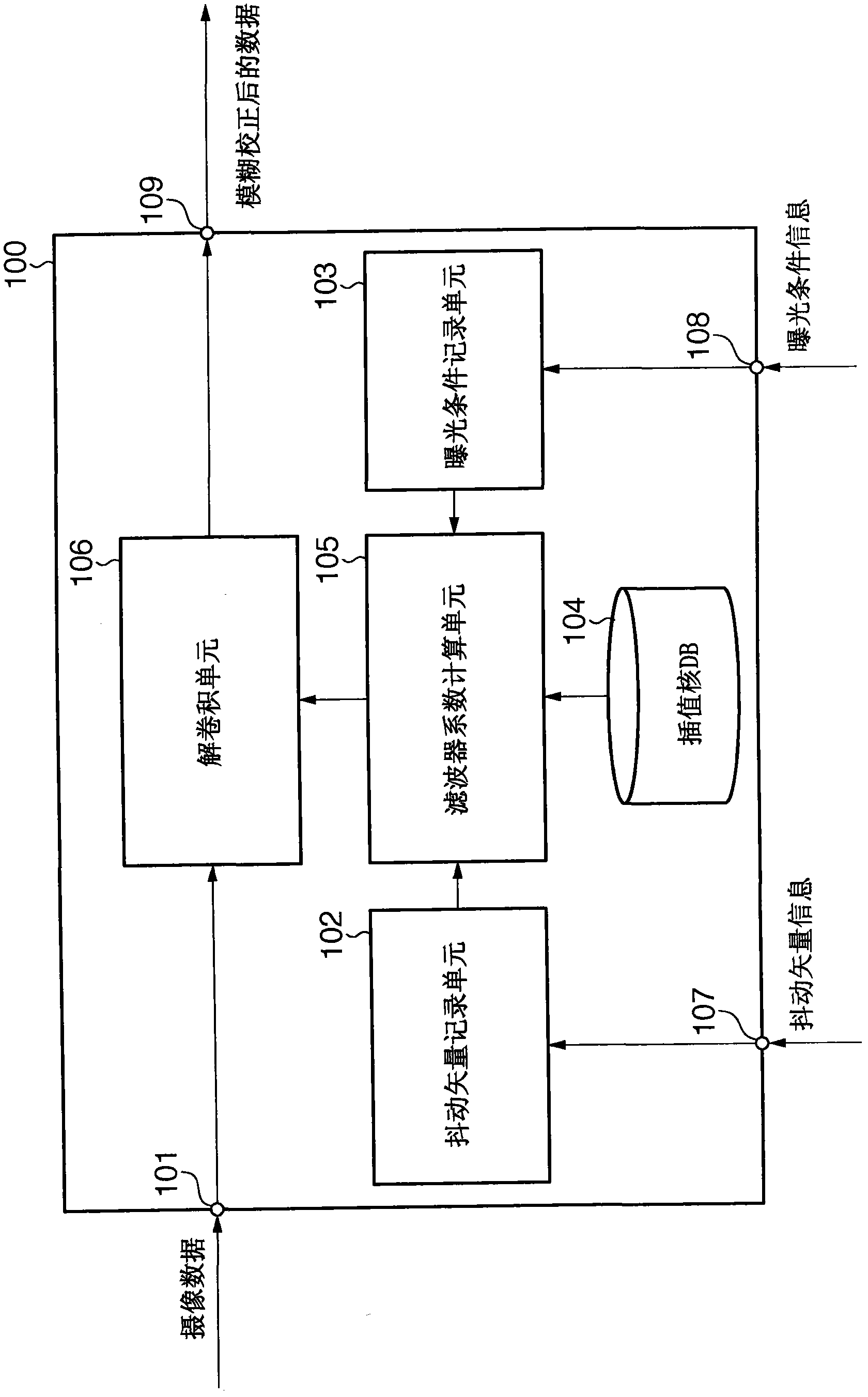
[0030] In this embodiment, an image processing device for correcting blur from one image will be described. Note that in this embodiment, camera shake is limited to translational shake. First, refer to figure 1 , to describe an example of the functional configuration of the correction unit 100 provided in the image processing apparatus according to the present embodiment. As described above, the correction unit 100 performs processing of correcting camera shake as translational shake from one image.
[0031] The imaging data (data of a captured image) is captured using an imaging device to input the captured imaging data to the input terminal 101 . In a subsequent stage, the image data is input to the deconvolution unit 106 . The dither vector recording unit 102 receives the dither vector information measured by another component of the image processing apparatus according to the embodiment via the input terminal 107 and records the received dither vector informa...
no. 2 example
[0108] In this embodiment, an imaging system incorporating the image processing device described in the first embodiment will be explained. The following will refer to Figure 8 , to describe an example of the functional configuration of the imaging unit 1100 equipped in the imaging system according to this embodiment.
[0109] The light reflected by the imaging target enters the image sensor 1104 through the input terminal 1101 , the lens 1102 , and the shutter 1103 . The image sensor 1104 outputs an analog signal corresponding to incident light. The A / D converter 1105 converts an analog signal into a digital signal. The digital signal is input to the correction unit 100 via the output terminal 1109 as imaging data.
[0110] An exposure condition setting unit 1106 sets exposure conditions. Information representing the set exposure conditions is input to the shutter 1103 as exposure condition information, and is also input to the correction unit 100 via the output terminal...
no. 3 example
[0114] In the second embodiment, optical anti-vibration is not taken into consideration. However, in the third embodiment, an imaging system combined with optical anti-vibration will be described. Below, will refer to Figure 9 , to describe an example of the functional configuration of the imaging unit 1200 equipped in the imaging system according to this embodiment. exist Figure 9 in, with Figure 8 The same reference numerals in the Figure 8 The description of the same parts will not be repeated here.
[0115] Image sensor movement detection unit 1201 detects movement of image sensor 1104 , and outputs the detection result as image sensor movement information to subtractor 1203 via output terminal 1202 . The subtractor 1203 subtracts the image sensor movement information detected by the image sensor movement detection unit 1201 from the shake vector information detected by the orientation detection unit 1107 . The subtraction result is input to the correction unit 1...
PUM
 Abstract
Description
Claims
Application Information
 - R&D Engineer
- R&D Manager
- IP Professional
- Industry Leading Data Capabilities
- Powerful AI technology
- Patent DNA Extraction
Browse by: Latest US Patents, China's latest patents, Technical Efficacy Thesaurus, Application Domain, Technology Topic, Popular Technical Reports.
© 2024 PatSnap. All rights reserved.Legal|Privacy policy|Modern Slavery Act Transparency Statement|Sitemap|About US| Contact US: help@patsnap.com