Bidirectional output unidirectional clutch mechanism

A one-way clutch, two-way output technology, applied in the field of mechanical transmission, can solve the problems of difficult mass production, inability to achieve two-way work, one-way disengagement, and only one-way output of power.

Active Publication Date: 2011-06-08
SINONEWENERGY SUZHOU TECH
View PDF8 Cites 9 Cited by
  • Summary
  • Abstract
  • Description
  • Claims
  • Application Information

AI Technical Summary

Problems solved by technology

When the power output part of the clutch (inner ring or outer ring) rotates faster than the power source (outer ring or inner ring), the clutch is in a disengaged state. Based on this, the overrunning clutch function of the overrunning clutch mechanism is realized. Due to the current one-way The device is mainly a spline cam type overrunning clutch, the patent number is ZL03233130.4, the name is "speed change gear device with cam type overrunning characteristics" and the patent number is ZL201010539253.8, the name is "single two-way clutch mechanism" clutch, it Including the gear, a spline cam is installed at the center of the gear. The circumference of the spline cam is evenly distributed with a plurality of sections of smooth curved surfaces with lifting characteristics. Cage, rollers are installed in the evenly divided gap of the cage, and each roller corresponds to a smooth curved surface of the spline cam with lifting c

Method used


Image

  • Bidirectional output unidirectional clutch mechanism
  • Bidirectional output unidirectional clutch mechanism

Examples


Embodiment 1

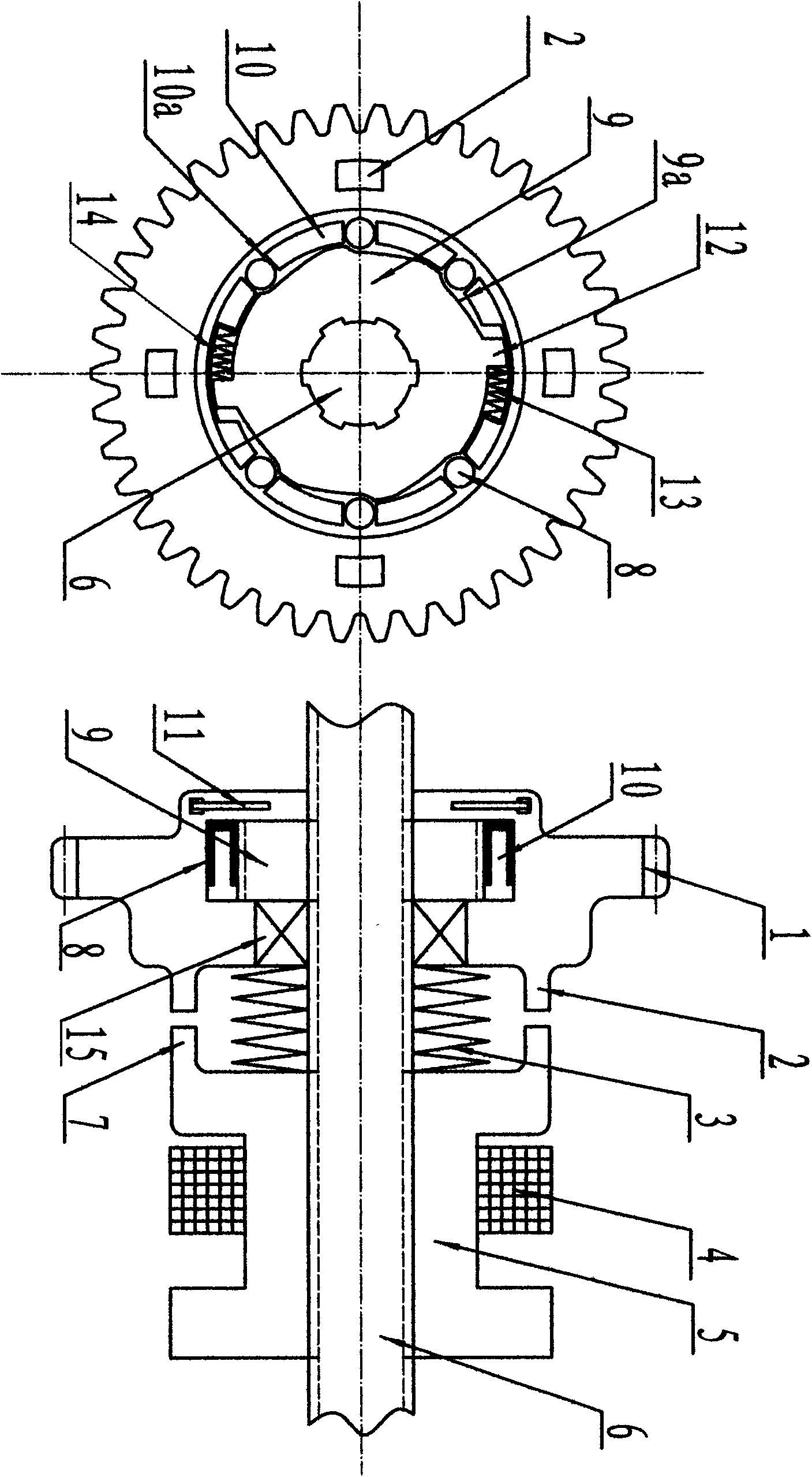
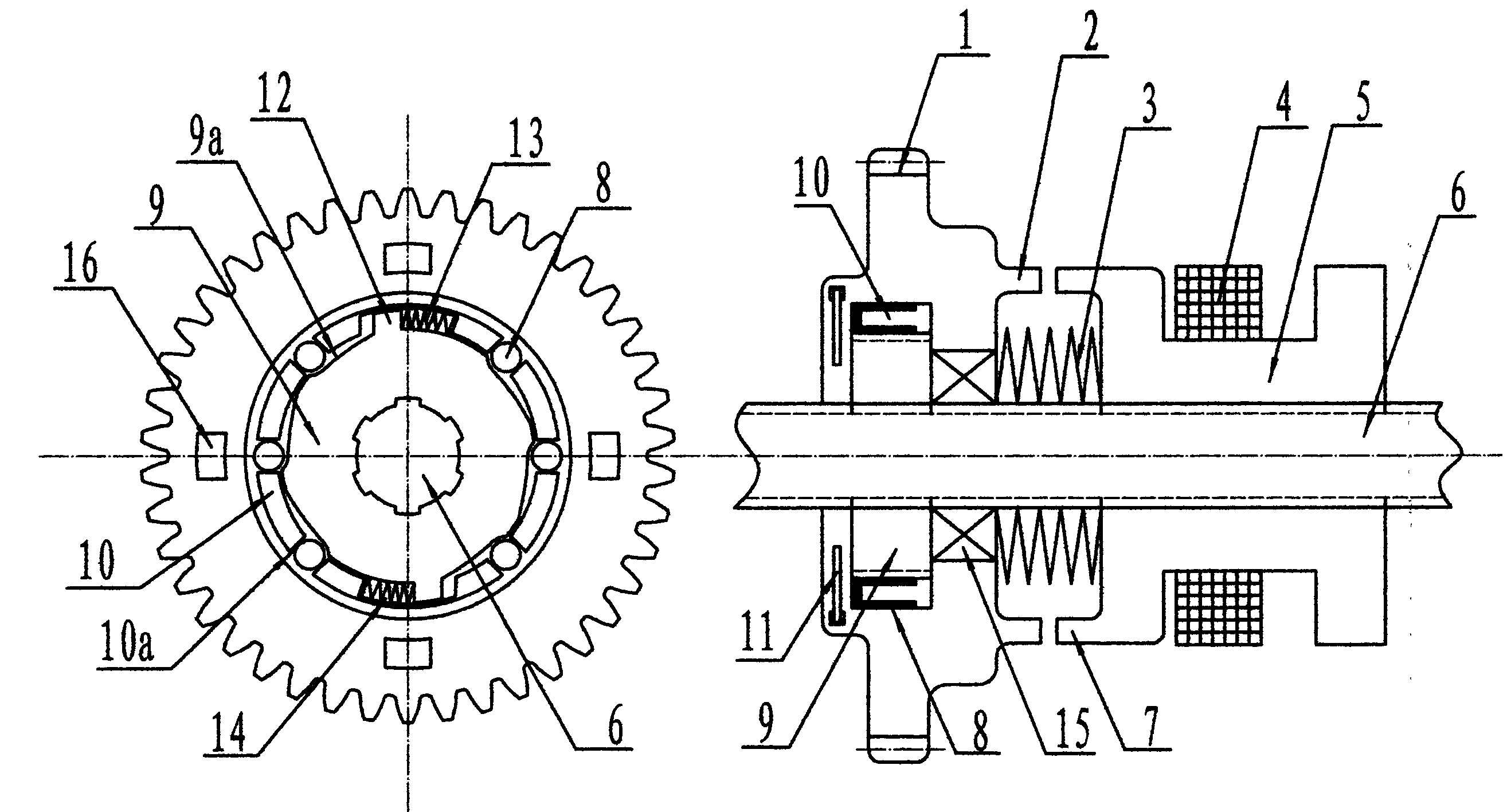
[0012] Such as figure 1 The shown two-way output one-way clutch mechanism includes a gear 1, the right part of the gear 1 is set on the transmission shaft 6 through a positioning bearing 15, and a spline cam 9 is installed at the center of the left part of the gear 1, and the spline The cam 9 is fitted on the transmission shaft 6 through a spline, and a cage 10 is installed between the spline cam 9 and the inner wall of the gear 1. On the outer circumference of the spline cam 9, a group of cam surfaces 9a and two cam surfaces are evenly distributed. Two bosses 12, and the two bosses 12 are arranged opposite, wherein the cam curved surface 9a is a smooth curved surface with lift characteristics, and each cam curved surface 9a is distributed clockwise on the splined cam 9 On the outer circumference of the spline cam 9, of course, each cam curved surface 9a is also distributed counterclockwise on the outer circumference of the spline cam 9, as long as each cam curved surface 9a i...


PUM


Abstract

The invention discloses a bidirectional output unidirectional clutch mechanism. The external periphery of a spline cam is respectively provided with a group of cam surfaces and convex columns uniformly, wherein the cam surfaces are circular and smooth with a lifting property, and each cam surface is distributed on the external periphery of the spline cam in the same rotation direction; a retaineris respectively uniformly provided with corresponding roller column installation gaps and radial compressed spring installation gaps; each roller column installation gap is internally provided with aroller column and a radial compressed spring; the radial compressed springs can enable the retainer to push the roller columns to the lifting direction of the cam surfaces; and each end surface of each gear is provided with a clamp bench, a spline housing spine set mechanism is fixedly sleeved on a transmission shaft at the outer side of the clamp bench, and the spline housing spine set in the spline housing spine set mechanism is clamped with the clamp benches of the gears. According to the invention, the function of the bidirectional output unidirectional clutch mechanism provided by the invention can be preferably realized through the gears and the spline housing spine set mechanism.

Description

technical field [0001] The invention belongs to the technical field of mechanical transmission, and in particular relates to a one-way clutch mechanism capable of realizing bidirectional output. Background technique [0002] In the existing overrunning clutch mechanism, an important part is a spline cam one-way device with a spline groove, because the one-way device can only rotate in one direction and lock in the other direction. When the power output part of the clutch (inner ring or outer ring) rotates faster than the power source (outer ring or inner ring), the clutch is in a disengaged state. Based on this, the overrunning clutch function of the overrunning clutch mechanism is realized. Due to the current one-way The device is mainly a spline cam type overrunning clutch, the patent number is ZL03233130.4, the name is "speed change gear device with cam type overrunning characteristics" and the patent number is ZL201010539253.8, the name is "single two-way clutch mechanis...

Claims


Application Information

Patent Timeline
IPC IPC(8): F16D41/064F16D41/08
Inventor 申念
Owner SINONEWENERGY SUZHOU TECH
Why Eureka
Try Eureka