
Supporting frame

A support frame and support rod technology, which is applied in the field of support frames, can solve the problems such as the inability of items to be stably placed and fixed in the required position and the unsatisfactory use.

Inactive Publication Date: 2011-06-08
李雪平
View PDF0 Cites 3 Cited by
  • Summary
  • Abstract
  • Description
  • Claims
  • Application Information

AI Technical Summary

Problems solved by technology

[0002] Generally, the structure of the existing support frame is a vertical part fixed on the wall, and one end of the vertical part is fixed with a parallel part perpendicular to it and extending in the horizontal direction, and a support rod is connected to the free end of the vertical part , the other end of the support rod is connected to the free end of the parallel part, so that the support rod can be connected with the vertical part and the parallel part. In this way, although the support of the support rod can increase the support of the parallel part However, because the parallel part is fixed with the vertical part and the support rod, if the surface of the place where the vertical part is fixed is uneven, the parallel part perpendicular to it will also tilt with it, and then the part fixed on the flat part will be inclined. Items cannot be placed in the desired position smoothly, which is very unsatisfactory in use

Method used


Image

  • Supporting frame
  • Supporting frame
  • Supporting frame

Examples


Embodiment Construction

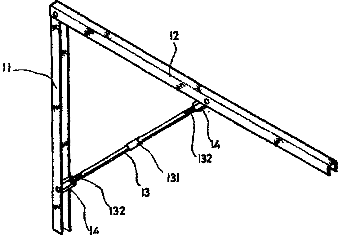
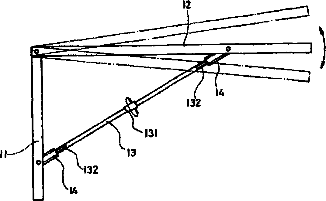
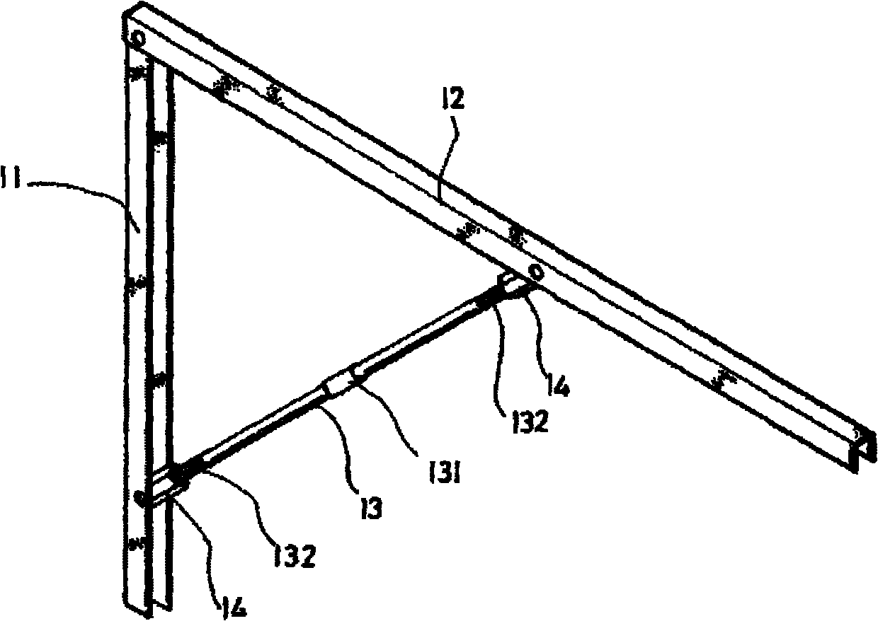
[0006] see figure 1 As shown, the present invention relates to a support frame, which mainly refers to a frame body 10 for supporting objects and whose angle can be adjusted. The frame body 10 is provided with a first pole 11, and one end of the first pole 11 is connected to a There is a second pole 12 extending in the horizontal direction, and on the free ends of the first and second poles 11, 12, opposite screw components 14 are respectively provided. In this embodiment, it is a nut. A support rod 13 is screwed on the component 14, and the support rod 13 is provided with a polygonal clamping portion 131 at a certain position, and the two ends of the support rod 13 are respectively provided with threads 132 that can cooperate with the screw assembly 14, The supporting rod 13 can be combined with the first and second supporting rods 11 and 12 by screwing the threads and the screwing component 14 together.

[0007] Please refer to figure 2 As shown, when the user fixes the f...


PUM


Abstract

The invention discloses a supporting frame. The supporting frame is a frame body with an adjustable angle, wherein the frame body is provided with a first support rod; one end of the first support rod is pivotally provided with a second support rod which is extended along the horizontal direction; the free ends of the first support rod and the second support rod are provided with a supporting rod respectively; the two ends of each supporting rod are sleeved on the first support rod, the second support rod and a threaded component which is matched with the first support rod and the second support rod respectively; when the first support rod is fixed, the two ends of the supporting rod are shrunk into the threaded component respectively by turning the supporting rod, or the free end of the second support rod gradually approaches inwards or outwards through outward protrusion in the threaded component; thus, the included angle between the first support rod and the second support rod is adjusted, and the second support rod can be moved to a required position.

Description

【Technical field】 [0001] The invention relates to a support frame, which is a rotating support rod to adjust the angle of the support rod for placing objects to meet actual needs. 【Background technique】 [0002] Generally, the structure of the existing support frame is a vertical part fixed on the wall, and one end of the vertical part is fixed with a parallel part perpendicular to it and extending in the horizontal direction, and the free end of the vertical part is connected with a support rod , the other end of the support rod is connected to the free end of the parallel part, so that the support rod can be connected with the vertical part and the parallel part. In this way, although the support of the support rod can increase the support of the parallel part However, because the parallel part is fixed with the vertical part and the support rod, if the surface of the place where the vertical part is fixed is uneven, the parallel part perpendicular to it will also tilt wit...

Claims


Application Information

Patent Timeline
IPC IPC(8): F16M13/02
Inventor 李雪平
Owner 李雪平
Learn More