Solar power generation device

A power generation device and sunlight technology, applied in photovoltaic power generation, circuits, electrical components, etc., can solve problems such as difficulty in realizing automatic fault detection of solar cell panels, difficulties in visual confirmation of light emission, and obstacles in solar cell panel fault detection.

Inactive Publication Date: 2011-06-08
MITSUBISHI ELECTRIC CORP
View PDF4 Cites 98 Cited by
  • Summary
  • Abstract
  • Description
  • Claims
  • Application Information

AI Technical Summary

Problems solved by technology

Therefore, there are problems as follows: it is difficult to automate the failure detection of the solar battery panel, and when the solar battery module is installed on the roof or in a remote place, it becomes difficult to visually confirm the light emission itself, which has a negative impact on the failure detection of the solar battery panel. obstacle

Method used


Image

  • Solar power generation device
  • Solar power generation device
  • Solar power generation device

Examples


Embodiment 1

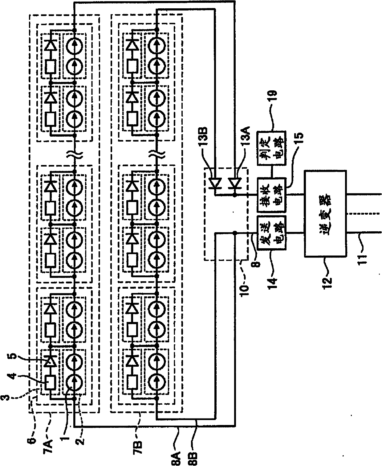
[0037] figure 1 It is a block diagram showing a schematic configuration of Embodiment 1 of the photovoltaic power generation device of the present invention. exist figure 1 In the solar power generation device, solar cell strings 7A and 7B in which solar cell modules 6 are electrically connected in series are provided. In addition, the solar cell modules 6 may constitute hardware-based separate units, and may be installed or replaced for each solar cell module 6 .

[0038] In addition, power lines 8A and 8B are led out from the solar cell strings 7A and 7B, respectively, and these power lines 8A and 8B are commonly connected to the power line 8 to connect the solar cell strings 7A and 7B in parallel.

[0039] Here, the solar cell module 6 is provided with a solar cell 1 that generates electricity from sunlight and a bypass circuit 3 , and one or more solar cell 1 are electrically connected in series or in parallel to form a connection unit 2 . . In addition, a bypass circuit...

Embodiment 2

[0099] Figure 7 It is a block diagram showing a schematic configuration of Embodiment 2 of the photovoltaic power generation device of the present invention. exist Figure 7 In this solar power generation device, in addition to figure 1 In addition to the structure of the solar power generation device, attenuation circuits 32A and 32B are also provided. In addition, as the attenuation circuits 32A and 32B, band-pass filters that pass only periodic signals with a frequency within a certain range can be used. Here, the attenuation circuit 32A is connected to the power line 8A on the side where the current flows into the solar cell string 7A, and the attenuation circuit 32B is connected to the power line 8B on the side where the current flows into the solar cell string 7B. Furthermore, the frequency bands of the periodic signals that can pass between the attenuation circuits 32A and 32B may be different, the attenuation circuit 32A may pass only the frequency band of the peri...

Embodiment 3

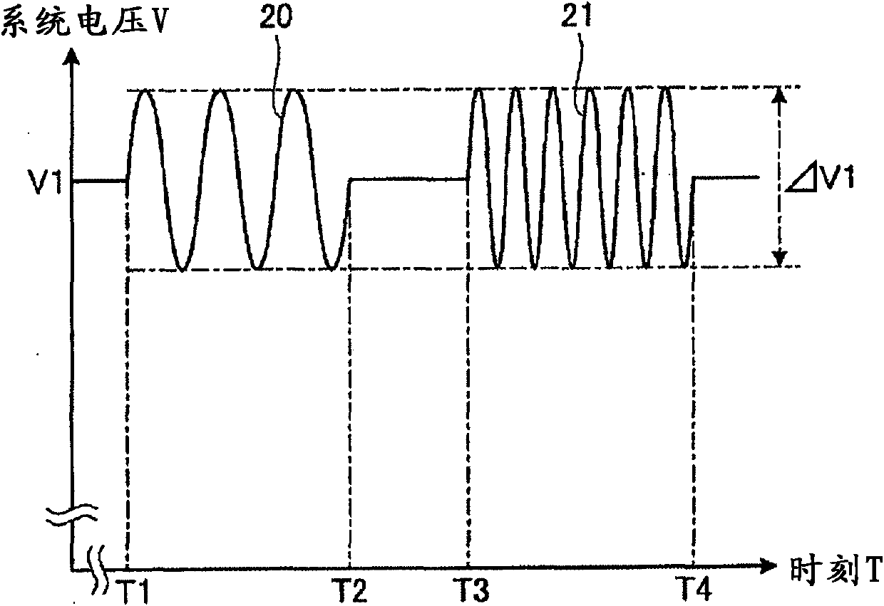
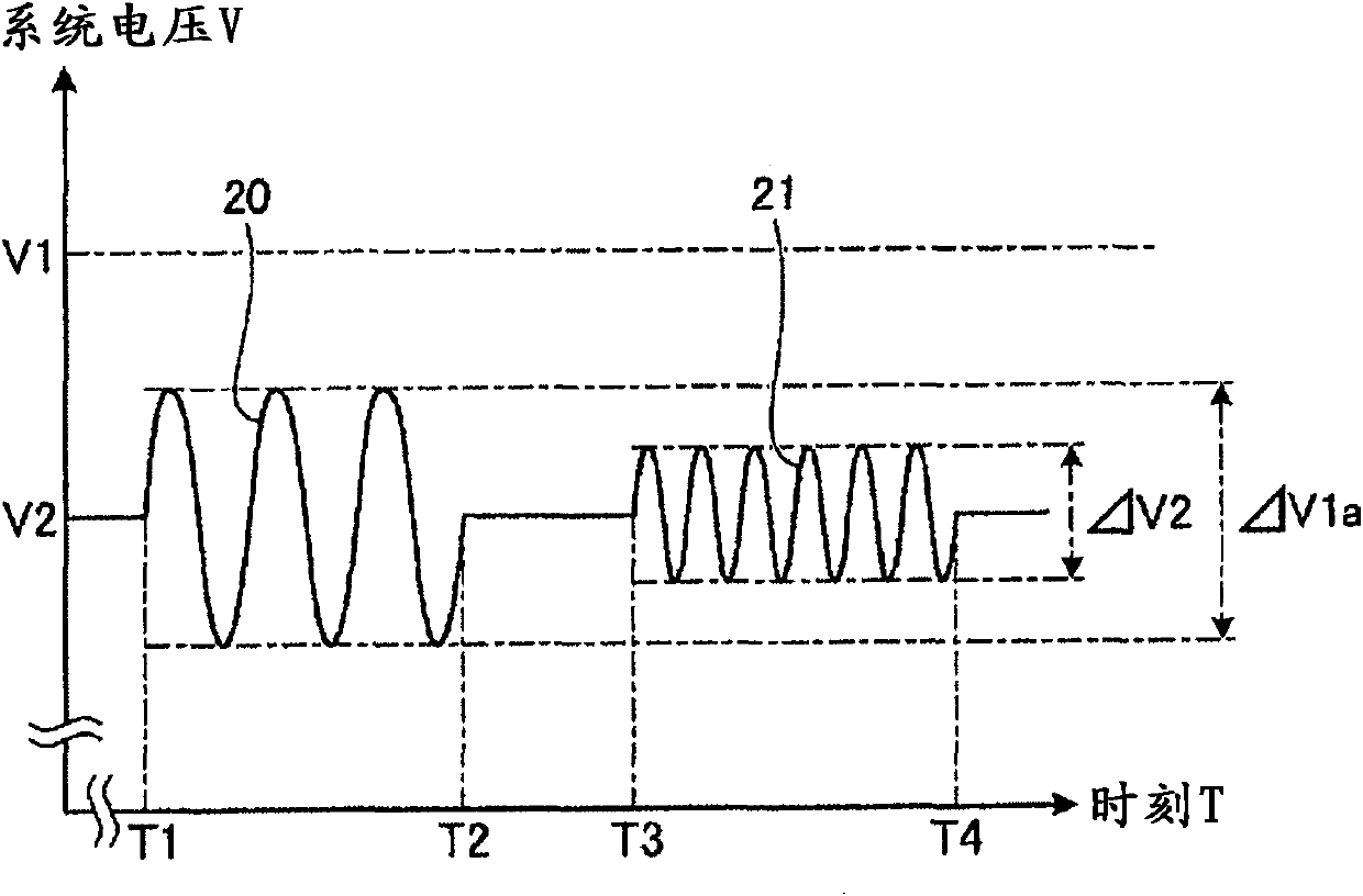
[0112] Figure 8 It is a block diagram showing a configuration example of the bypass power line 9A applied to the third embodiment of the photovoltaic power generation device of the present invention. exist Figure 8 Among them, on the input side and the output side of the attenuation circuit 32A, switchover switches 34 and 35 for bypassing the attenuation circuit 32A on the power line 8A and a bypass power line 9A are provided, respectively. In addition, the same configuration may be provided for the attenuation circuit 32B.

[0113] In addition, when periodic signals 20 and 21 are sent to solar cell strings 7A and 7B, attenuation circuits 32A and 32B can be temporarily energized by switching switches 34 and 35 to the attenuation circuits 32A and 32B side.

[0114] Thereby, the attenuation circuits 32A, 32B can be energized only when the failure of the solar cell 1 is checked, and the attenuation circuits 32A, 32B can be prevented from being energized all the time, so that ...


PUM


Abstract

A transmission circuit (14) is connected onto an electric power line (8) at the side of the inflow of current to solar battery strings (7A, 7B) and a reception circuit (15) is connected onto the electric power line (8) at the side of the outflow of current to the solar battery strings (7A, 7B). Then, an attenuation circuit (4) connected in series with a bypass diode (5) is provided on a bypass circuit (3). The transmission circuit (14) transmits a periodic signal with a predetermined frequency to the electric power line (8). The reception circuit (15) receives a transmission signal transmitted from the transmission circuit (14) to the electric power line (8) via the solar battery strings (7A, 7B). A determination circuit (19) determines that direct-current power is distributed to the bypass circuit (3) when it is detected that the oscillation of the transmission signal received by the reception circuit (15) is attenuated by a predetermined value or more.

Description

technical field [0001] The present invention relates to a photovoltaic power generation device, and more particularly to a method for detecting a failure of a photovoltaic power generation device configured using a plurality of solar battery cells in order to obtain desired power. Background technique [0002] In a photovoltaic power generation device using solar cells, in order to obtain desired electric power, solar cell strings constituted by serially connecting solar cell modules equipped with solar cells are connected in parallel. Here, when a solar cell installed in a solar cell module fails or sunlight is blocked and the electromotive force of the solar cell becomes lower than a specified value, in order to prevent interference with other solar cells connected in series with the solar cell, For the energization of the battery cells, a bypass circuit (bypass circuit) is connected in parallel for each connection unit in which one or more solar battery cells are electric...

Claims


Application Information

Patent Timeline
Patent Type & Authority Applications(China)
IPC IPC(8): H01L31/04
CPCY02E10/50H01L31/02021
Inventor 高野富裕藤塚正史西尾直树岛田直人
Owner MITSUBISHI ELECTRIC CORP
Why Eureka
Try Eureka