System for testing linear motor characteristics
A linear electromagnetic and characteristic testing technology, applied in motor generator testing, asynchronous inductive clutch/brake, etc., can solve the problems of inability to change continuously, testing loading force in one direction, etc.
- Summary
- Abstract
- Description
- Claims
- Application Information
AI Technical Summary
Problems solved by technology
Method used
Image
Examples
specific Embodiment approach 1
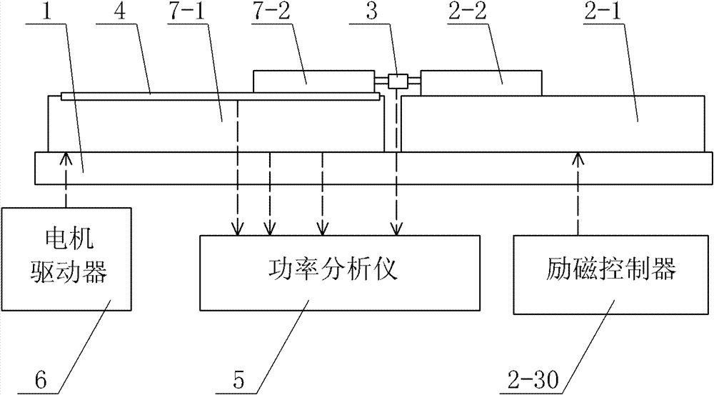
[0084] Specific implementation mode one: the following combination Figure 1 to Figure 7 Describe this embodiment, this embodiment is made up of system platform 1, linear electromagnetic damper, force sensor 3, speed sensor 4, power analyzer 5 and motor driver 6,
[0085] The motor stator 7-1 of the motor under test and the damper stator 2-1 of the linear electromagnetic damper are set on the system platform 1 at the same time, and the relative positions of the motor stator 7-1 and the damper stator 2-1 remain constant. Change,
[0086] The power output end of the motor driver 6 is connected to the armature winding input end of the motor under test, and the armature winding output end of the motor under test is respectively connected to the current input end and the voltage input end of the power analyzer 5,
[0087] The force sensor 3 is used to detect the interaction force between the motor mover 7-2 of the motor under test and the damper mover 2-2 of the linear electromagn...
specific Embodiment approach 2
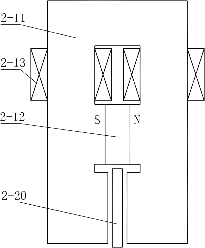
[0099] Specific implementation mode two: the following combination figure 2 Describe this embodiment. This embodiment is a further description of Embodiment 1. The linear electromagnetic damper is a double-sided single-primary structure.
[0100] The iron core 2-11 forms a gate-shaped structure by a horizontal section and two vertical core columns. The middle part of the horizontal section is wound with an excitation coil 2-13 or the upper section of each vertical core is wound with an excitation coil 2-13, two The permanent magnet 2-12 is clamped between the middle sections of the vertical core columns, the secondary 2-20 is arranged between the inner side walls of the lower section of the two vertical core columns, and the secondary 2-20 is connected to the lower section of the two vertical core columns. Air gaps are respectively formed between the inner side walls. Other components and connections are the same as those in Embodiment 1.
[0101] figure 2 The excitation ...
specific Embodiment approach 3
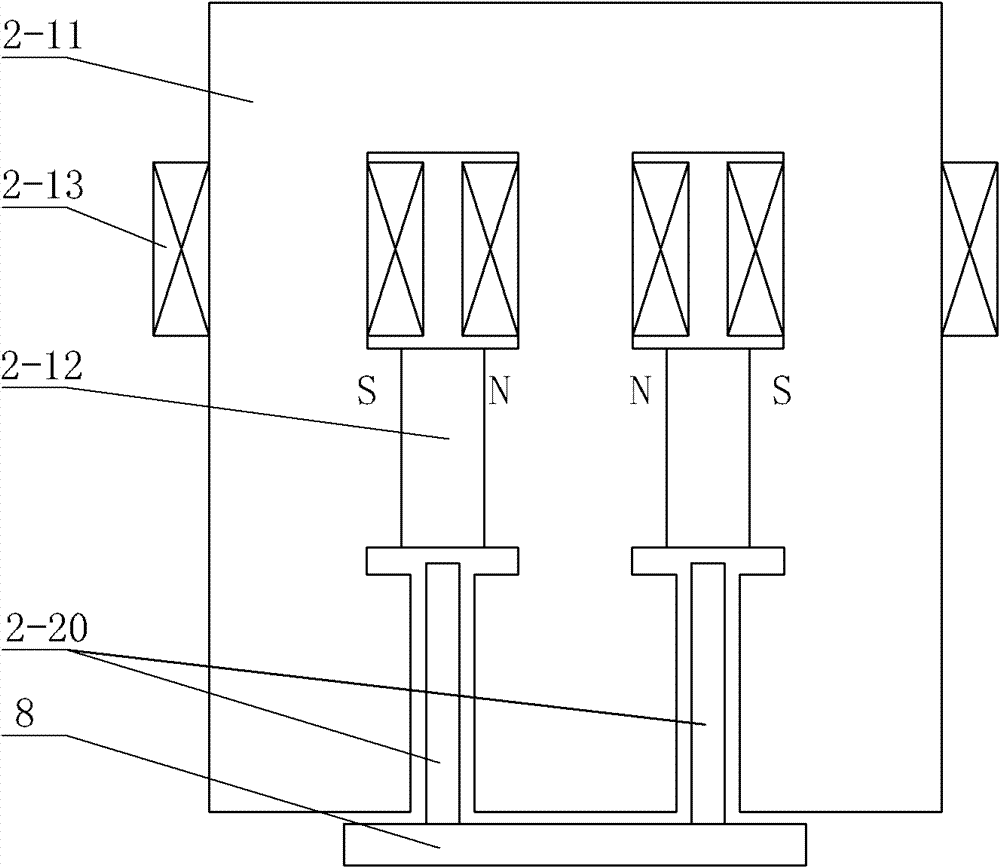
[0103] Specific implementation mode three: the following combination image 3 Describe this embodiment. This embodiment is a further description of Embodiment 1. The linear electromagnetic damper is a double-sided single-primary parallel structure.
[0104]The iron core 2-11 forms a comb structure of N-1 teeth by a horizontal section and N vertical columns, N is a natural number greater than or equal to 3, and the horizontal section between each adjacent two vertical columns An excitation coil 2-13 is wound in the middle or an excitation coil 2-13 is wound on the upper section of each vertical core column, and a permanent magnet 2-12 is clamped between the middle sections of each adjacent two vertical core columns, and each adjacent A secondary 2-20 is set between the inner walls of the lower section of the two vertical columns, and air gaps are formed between each secondary 2-20 and the inner walls of the vertical columns on both sides, N-1 secondary Stages 2-20 are fixedly ...
PUM
 Abstract
Description
Claims
Application Information
 - R&D
- Intellectual Property
- Life Sciences
- Materials
- Tech Scout
- Unparalleled Data Quality
- Higher Quality Content
- 60% Fewer Hallucinations
Browse by: Latest US Patents, China's latest patents, Technical Efficacy Thesaurus, Application Domain, Technology Topic, Popular Technical Reports.
© 2025 PatSnap. All rights reserved.Legal|Privacy policy|Modern Slavery Act Transparency Statement|Sitemap|About US| Contact US: help@patsnap.com


