Loading test device for dynamic braking linear motors

A linear motor and energy-consumption braking technology, which is applied in the direction of motor generator testing, etc., can solve the problems of non-continuous adjustment and unidirectional test loading force, etc., and achieve the effect of simple structure, elimination of loading force fluctuation, and high reliability

Active Publication Date: 2013-08-21
HARBIN INST OF TECH
View PDF4 Cites 0 Cited by
  • Summary
  • Abstract
  • Description
  • Claims
  • Application Information

AI Technical Summary

Problems solved by technology

[0005] In order to solve the problem that the existing linear motor thrust loading test device can only test in one direction and the loading force cannot be continuously adjusted, the present invention provides a dynamic braking type linear motor test loading device

Method used


Image

  • Loading test device for dynamic braking linear motors
  • Loading test device for dynamic braking linear motors
  • Loading test device for dynamic braking linear motors

Examples


specific Embodiment approach 1

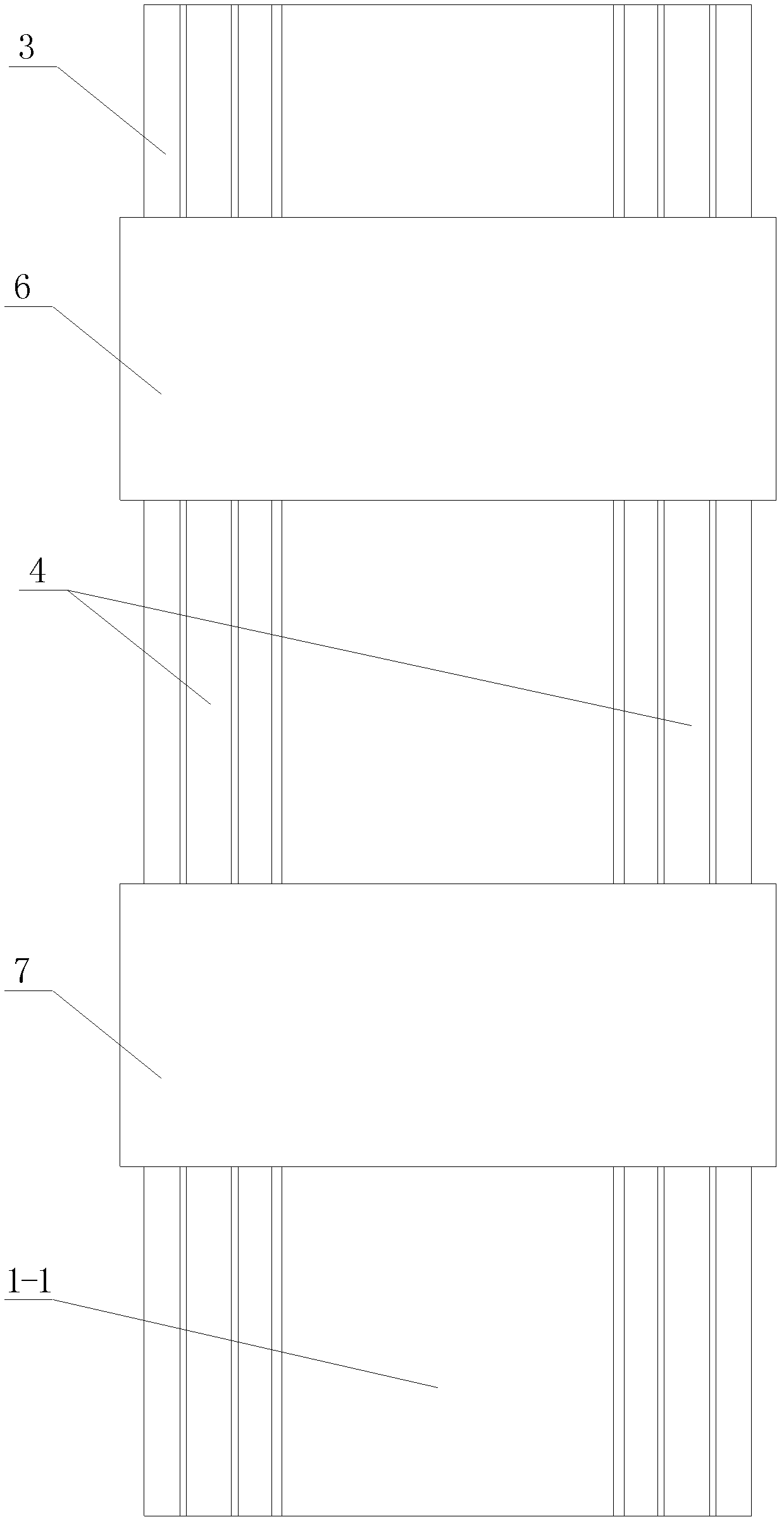
[0041] Specific implementation mode one: the following combination Figure 1 to Figure 4 Describe this embodiment, the dynamic braking type linear motor test loading device described in this embodiment includes a linear motor to be tested, and it also includes a linear brake for loading, a table body 3, a support guide rail 4, a sliding frame 6 for the motor under test, Load brake carriage 7, force transducer and displacement transducer,

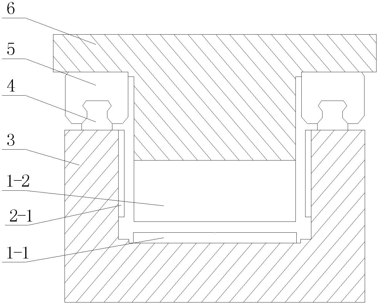
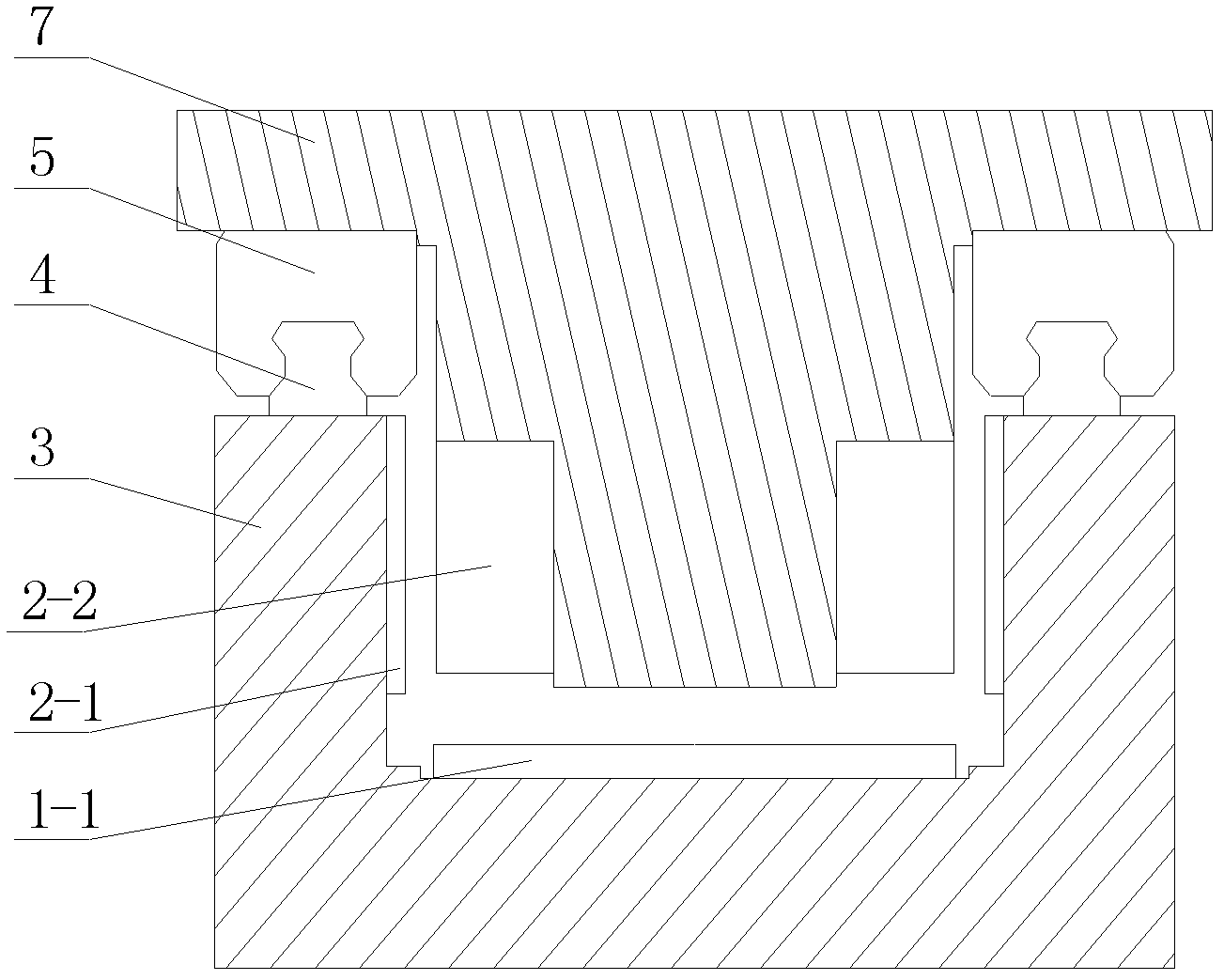
[0042] The table body 3 is a U-shaped structure, and support guide rails 4 are arranged symmetrically on the upper surfaces of the two vertical sections of the table body 3. The measuring motor sliding frame 6 is slidingly connected with the supporting rail 4 through the rail slider 5, and the loading brake sliding frame 7 is slidingly connected with the supporting rail 4 through the rail sliding block 5,

[0043] The motor stator 1-1 of the linear motor under test is fixedly installed on the inner surface of the horizontal section of the t...

specific Embodiment approach 2

[0048] Specific implementation mode two: the following combination Figure 5 and Figure 6 Describe this embodiment, the dynamic braking type linear motor test loading device described in this embodiment includes a linear motor to be tested, and it also includes a linear brake for loading, a table body 3, a main support guide rail 4, and a sliding frame 6 for the motor under test , load brake carriage 7, force sensor and displacement sensor,

[0049] The upper surface of the table body 3 is symmetrically provided with a main rail substrate 3-1, and the main rail substrate 3-1 divides the upper surface of the table body 3 into a left section, a middle section and a right section,

[0050] The main support rails 4 are arranged symmetrically on the upper surface of a pair of main rail substrates 3-1, the tested motor sliding frame 6 and the loading brake sliding frame 7 are all arranged on the main supporting rails 4, and the measured motor sliding frame 6 passes through the mai...

specific Embodiment approach 3

[0056] Specific implementation mode three: the following combination Figure 7 and Figure 8 Describe this embodiment. This embodiment is a further description of Embodiment 2. The test loading device described in this embodiment also includes an auxiliary support guide rail 8 and an auxiliary guide rail slider 9. The table body 3 also includes a pair of auxiliary guide rail substrates. 3-2,

[0057] A pair of auxiliary guide rail substrates 3-2 are arranged symmetrically on both sides of the table body 3, the auxiliary guide rail substrate 3-2 is parallel to the main guide rail substrate 3-1, and on the upper surface of the pair of auxiliary guide rail substrates 3-2 Auxiliary support guide rails 8 are arranged symmetrically, and the auxiliary support guide rails 8 are slidably connected with the loading brake sliding frame 7 through the auxiliary guide rail sliders 9 .

[0058] In this embodiment, an auxiliary guide rail base plate 3 - 2 is added to support the loading bra...


PUM


Abstract

The invention discloses a loading test device for dynamic braking linear motors and belongs to the technical field of motor test, solving the problem that in the existing linear motor thrust loading test device, only a unidirectional test can be performed, and a loading force can not be adjusted continuously. The device disclosed by the invention is characterized in that the platform body of the device is in a U-shaped structure, supporting guide rails are symmetrically arranged on the upper surfaces of the two vertical sections of the platform body, and a tested motor sliding bracket and a loading brake sliding bracket are both arranged on the supporting guide rails; a motor stator of a tested linear motor is fixedly arranged on the internal side face of the horizontal section of the platform body, and the motor rotor of the tested linear motor is fixedly arranged on the bottom end face of the tested motor sliding bracket; brake stators of a pair of loading linear brakes are symmetrically arranged on the internal side walls or external side walls of the two vertical sections of the platform body, and brake rotors of the pair of loading linear brakes are symmetrically arranged on the loading brake sliding bracket; and a force sensor is connected between the tested motor sliding bracket and the loading brake sliding bracket. The device disclosed by the invention is applicable to the loading test of linear motors.

Description

technical field [0001] The invention relates to a testing and loading device for a dynamic braking type linear motor, which belongs to the technical field of motor testing. Background technique [0002] In the field of modern processing industry, many occasions such as laser cutting, high-speed grinding machines, precision lathes, machining centers, etc. require high-speed and high-precision linear motion. The traditional method can only use intermediate links such as rotating motors and ball screws to obtain linear motion. Movement, which inevitably has disadvantages such as large inertia, large friction, and backlash. In recent years, with the development of linear motor technology, more and more occasions have begun to directly apply linear motors to obtain linear motion. Due to the use of direct drive technology, linear motors have the advantages of fast speed, high acceleration, high positioning accuracy, long stroke and fast dynamic response, which just meet the requi...

Claims


Application Information

Patent Timeline
Patent Type & Authority Patents(China)
IPC IPC(8): G01R31/34
Inventor 寇宝泉金银锡杨俊张海林
Owner HARBIN INST OF TECH
Why Eureka
Try Eureka