Optical fingerprint acquisition instrument without keystone distortions

A fingerprint collector and trapezoidal distortion technology, applied in optics, optical components, instruments, etc., can solve the problems of increased manufacturing cost, increased product size, optical path complexity, and reduced production efficiency, achieving small size and reduced product cost , Eliminate the effect of trapezoidal distortion

Inactive Publication Date: 2013-12-11
CHENGDU FINCHOS ELECTRONICS
View PDF0 Cites 0 Cited by
  • Summary
  • Abstract
  • Description
  • Claims
  • Application Information

AI Technical Summary

Problems solved by technology

However, the above method does not solve the root cause of image distortion. Since the condenser lens and image correction prism are installed separately, the size of the product and the complexity of the optical path will be increased, which will eventually lead to an increase in manufacturing costs and a decrease in production efficiency. reduce

Method used


Image

  • Optical fingerprint acquisition instrument without keystone distortions
  • Optical fingerprint acquisition instrument without keystone distortions
  • Optical fingerprint acquisition instrument without keystone distortions

Examples


specific Embodiment 1

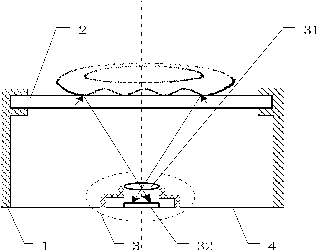
[0019] see figure 1 , figure 2 , image 3 , Figure 4 , the optical fingerprint collector without trapezoidal distortion of the present invention includes: a housing 1 , a collector board 2 , an imaging device 3 and a circuit board 4 .

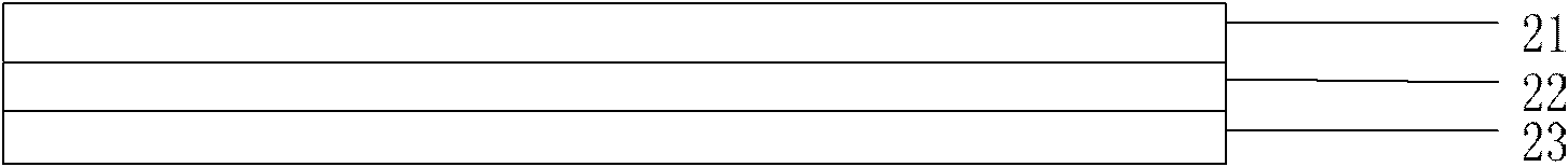
[0020] The collection plate 2 at least includes a transparent contact layer 21 and a transparent luminescent layer 22 , the transparent contact layer 21 is used for direct contact with fingers; the transparent luminescent layer 22 is located below the transparent contact layer 21 .

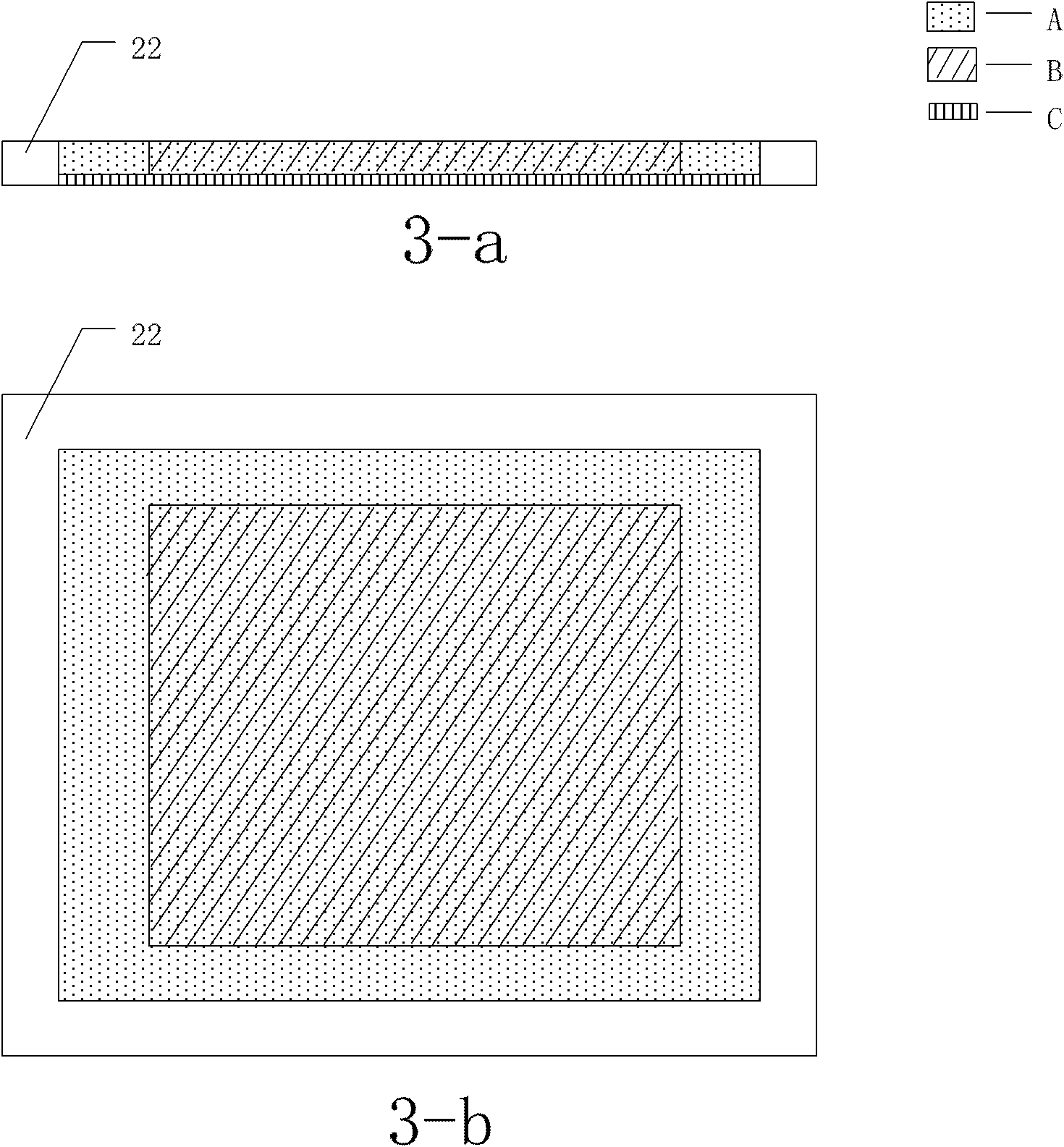
[0021] The transparent light-emitting layer 22 includes a collection light-emitting area A and a display light-emitting area B, which are electrically connected to the circuit board 4 respectively; the collection light-emitting area A of the transparent light-emitting layer 22 is a surface shape, located on the transparent contact layer 21 directly below the effective collection area (eg image 3 -a), its area is greater than or equal to the area of ​​the eff...

specific Embodiment 2

[0026] see figure 1 , figure 2 , Figure 5 , Figure 6 , the optical fingerprint collector without trapezoidal distortion of the present invention includes: a housing 1 , a collector board 2 , an imaging device 3 and a circuit board 4 .

[0027] The collection plate 2 at least includes a transparent contact layer 21 and a transparent luminous layer 22 , the transparent contact layer 21 is used for direct contact with fingers, and the transparent luminous layer 22 is located below the transparent contact layer 21 .

[0028] The transparent light-emitting layer 22 includes a collection light-emitting area A and a display light-emitting area B, and the collection light-emitting area A and the display light-emitting area B are electrically connected to the circuit board 4 respectively; The edge of the effective acquisition area (such as Figure 5 shown).

[0029] The collection board 2 also has a transparent protective layer 23, which is located under the transparent lumines...


PUM


Abstract

The invention provides an optical fingerprint acquisition instrument without keystone distortions. The optical fingerprint acquisition instrument comprises a shell, an acquisition board, an imaging device and a circuit board, and is characterized in that: the acquisition board at least comprises a transparent contact layer and a transparent luminescent layer which is positioned below the transparent contact layer; and the imaging device is positioned right blow the acquisition board. The optical fingerprint acquisition instrument uses the acquisition board as an acquisition component of fingerprint images, and the imaging device is positioned right below the acquisition board to ensure that the distances (optical distance) from an acquisition surface to imaging surfaces are accordant, and the keystone distortions of the fingerprint images are eliminated. The invention ensures that the whole product tends to a surface type and is small in size, the product cost is reduced and the application range is enlarged.

Description

technical field [0001] The invention relates to an optical fingerprint collector, in particular to an optical fingerprint collector without trapezoidal distortion. Background technique [0002] The optical fingerprint collection device is a fingerprint collection device widely used in the existing fingerprint identification system, which uses the optical difference caused by the difference of the ridge line and the valley line of the light on the interface to form an image and collect it. [0003] The optical fingerprint collector collects the surface texture image of the fingerprint. Specific light is irradiated on the surface of the finger to form reflected light. Since the ridges and valleys of the fingerprint are different, the amount of reflected light is also different. The reflected light passes through the imaging device Capture imaging. [0004] Since the collection device of the traditional optical fingerprint collection device usually uses a prism, the distance (...

Claims


Application Information

Patent Timeline
Patent Type & Authority Patents(China)
IPC IPC(8): G06K9/20G02B27/00
Inventor 李扬渊汪镜方丽君
Owner CHENGDU FINCHOS ELECTRONICS
Why Eureka
Try Eureka