
Peristaltic pump structure

A peristaltic pump and pump body technology, applied in the field of peristaltic pumps, can solve the problems of reducing the extrusion effect of peristaltic pumps, not firmly snapping off, not fixing the hose, etc.

Inactive Publication Date: 2011-06-22
CHANGZHOU PREFLUID TECH
View PDF5 Cites 4 Cited by
  • Summary
  • Abstract
  • Description
  • Claims
  • Application Information

AI Technical Summary

Problems solved by technology

[0002] The peristaltic pump is a rolling component driven by the motor to squeeze the liquid in the hose, so that the liquid is squeezed out of the hose. The rolling rollers on the rolling component of the traditional peristaltic pump use two upper and lower cover plates They are snapped together, and the rolling rollers are connected between the upper and lower cover plates. If the upper and lower cover plates are used for a long time, they will often be disengaged due to weak engagement, and the peristaltic pump will lose its function. , which affects the service life; and the traditional peristaltic pump slot only plays the role of placing the hose, and does not fix the hose. During the process of squeezing the hose by the roller assembly, the hose rotates with the roller assembly. movement, reducing the squeezing effect of the peristaltic pump

Method used


Image

  • Peristaltic pump structure
  • Peristaltic pump structure
  • Peristaltic pump structure

Examples


Embodiment Construction

[0014] The present invention will be further described in detail below with reference to the embodiments given in the drawings.

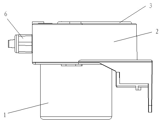
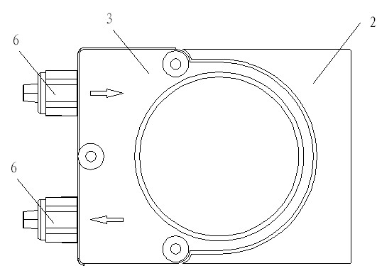
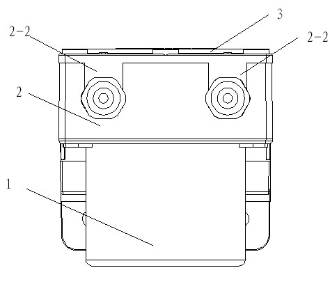
[0015] See figure 1 , 2 , 3, 4, 5, and 6, a peristaltic pump structure includes a motor 1, a pump body 2, an upper cover 3, a rolling assembly 4, and a hose 5. The motor 1 is fixedly connected to one end of the pump body 2, and the pump The other end of the body 2 has a squeezing cavity 2-1, the rolling assembly 4 and the hose 5 are located in the squeezing cavity 2-1, and the hose 5 surrounds the rolling assembly 4, and the motor 1 is connected to the rolling assembly 4 in transmission, The upper cover 3 is fixedly connected to the other end of the pump body 2, and the inlet end 5-1 and the outlet end 5-2 of the hose 5 extend out of the pump body 2. The rolling assembly 4 includes a rolling roller 4-1 and a bracket 4-2. Both the upper and lower ends of the bracket 4-2 have radial wings 4-2-1, and the upper end of the rolling roller of the rolling asse...


PUM


Abstract

The invention discloses a peristaltic pump structure which comprises a motor, a pump body, an upper cover, a rolling component and a hose, wherein the motor is fixedly connected with one end of the pump body, an extrusion cavity is arranged at the other end of the pump body, the rolling component and the hose are both arranged in the extrusion cavity, the hose surrounds the rolling component, the motor is in transmission connection with the rolling component, the upper cover is fixedly connected with the other end of the pump body, the inlet end and the outlet end of the hose extend out of the pump body, the rolling component comprises a rolling roller and a bracket, radial convex wings are respectively arranged at the upper end and the lower end of the bracket, the upper end of the rolling component is connected to the radial convex wing arranged at the upper end of the bracket, the lower end of the rolling component is connected to the radial convex wing arranged at the lower end of the bracket, and fixing joints are respectively arranged at the inlet end and the outlet end of the hose and are installed in a locking installation groove of the pump body in a locking way. The invention has good extrusion effect and long service life.

Description

Technical field [0001] The invention relates to a peristaltic pump, particularly a peristaltic pump suitable for outputting washing liquid of washing machines and dishwashers. Background technique [0002] The peristaltic pump is a rolling component driven by the motor, squeezes the liquid in the hose, so that the liquid is squeezed out of the hose. The rolling roller on the rolling component of the traditional peristaltic pump uses two upper and lower cover plates. Clamped together, the rolling roller is installed between the upper and lower cover plates. If the upper and lower cover plates are used for a long time, it will often cause the disengagement due to the looseness of the clamping and the peristaltic pump will lose its function. , Which affects the service life; and the traditional peristaltic pump clamping groove only plays the role of placing the hose, and does not fix the hose. During the process of the hose being squeezed by the roller assembly, the hose changes wit...

Claims


Application Information

Patent Timeline
IPC IPC(8): F04B43/12
Inventor 沈留训侯鲁成
Owner CHANGZHOU PREFLUID TECH
Learn More