Anti-dropping sealing structure connected between corrugated pipes

A sealing structure and bellows technology, applied in the direction of sleeve/socket connection, pipe/pipe joint/pipe fitting, passing element, etc., can solve the problems of poor sealing effect, high engineering cost, pipe detachment, etc., and achieve enhanced sealing Effectiveness, long service life and reliable fixation

Inactive Publication Date: 2019-11-08
KANGMINGYUAN GUIZHOU SCI & TECH DEV CO LTD
View PDF0 Cites 2 Cited by
  • Summary
  • Abstract
  • Description
  • Claims
  • Application Information

AI Technical Summary

Problems solved by technology

In this connection method, due to the elasticity of the sealing ring, the sealing ring will drive the axial rebound of the pipe after insertion, which will make the sealing effect worse. In addition, due to geological subsidence in the later stage, it will generate tension on the pipe and make the pipe disengage.
The flange connection method requires many connection parts such as flanges and bolt assemblies, which is troublesome to install and high in engineering cost.

Method used


Image

  • Anti-dropping sealing structure connected between corrugated pipes
  • Anti-dropping sealing structure connected between corrugated pipes
  • Anti-dropping sealing structure connected between corrugated pipes

Examples


Embodiment 1

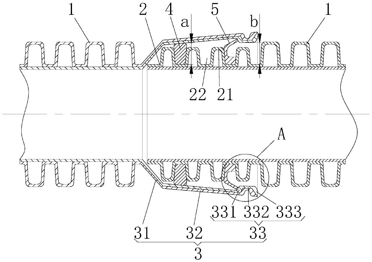
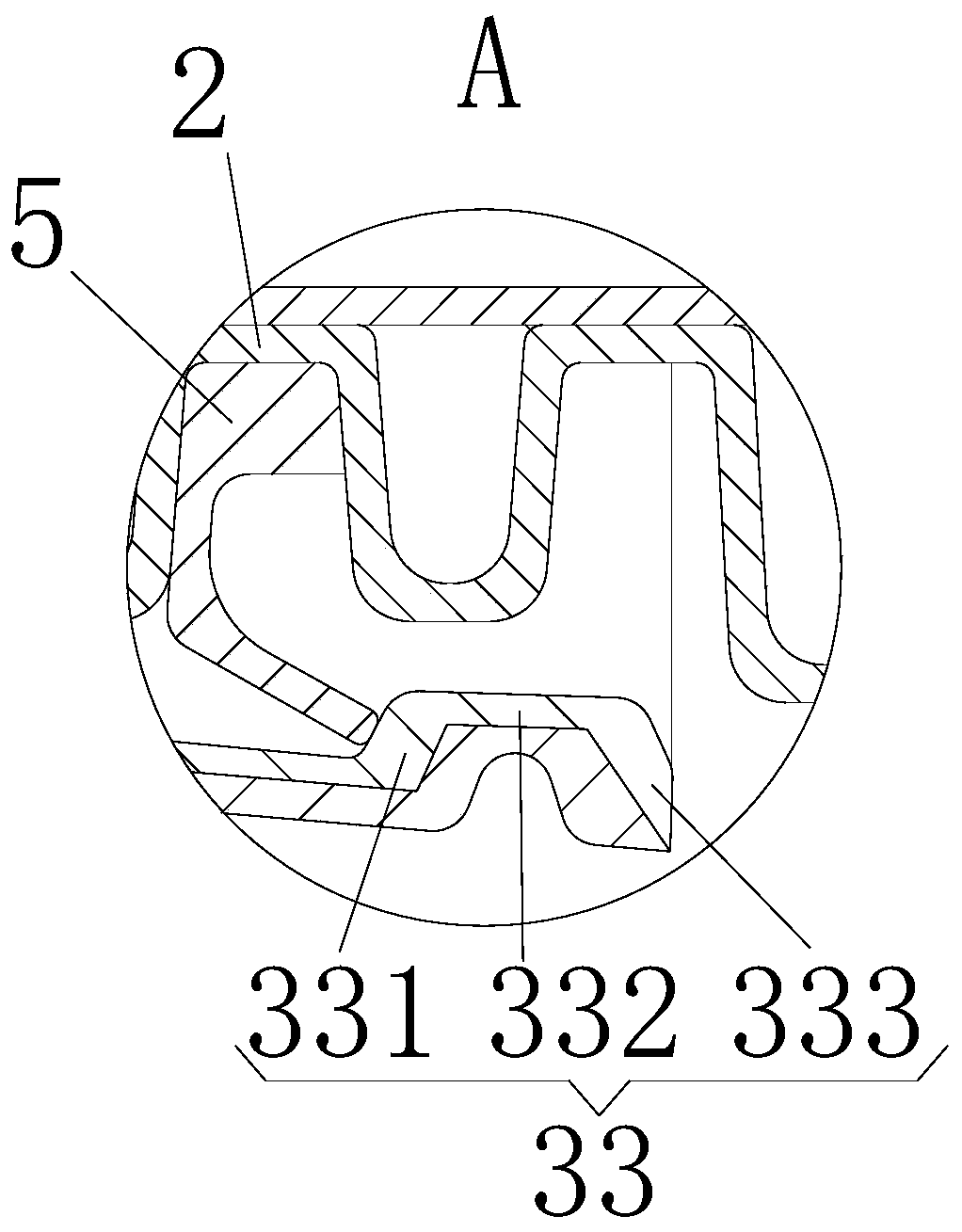
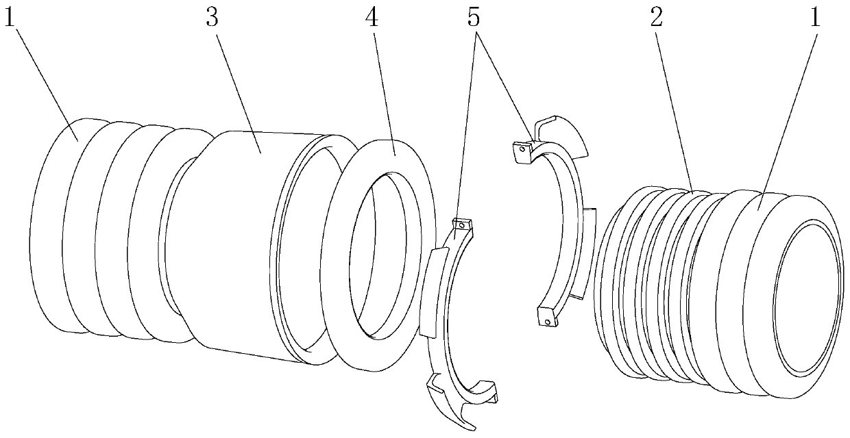
[0028] Such as Figure 1-4 Shown is an anti-off sealing structure for the connection between bellows provided in this embodiment, including a socket section 2 fixedly connected to the port of one section of bellows 1, and a socket section 2 fixedly connected to the port of another section of bellows 1 for The socket section 3 mated with the socket section 2, the sealing ring 4 arranged between the socket section 2 and the socket section 3, and the anti-off piece 5 arranged between the socket section 2 and the socket section 3; The outer peripheral wall of the socket section 2 has a corrugated structure in which crests 21 and troughs 22 are arranged alternately in the axial direction, the sealing ring 4 is arranged in a wave trough 22 at the front end of the socket section 2, and the anti-dropping member 5 is arranged on the socket section 2 in a trough 22 at the rear end, the socket section 3 includes a limiting section 31, a receiving section 32 and a clamping section 33 arra...

Embodiment 2

[0036] Such as Figure 5 As shown, the difference between Embodiment 2 and Embodiment 1 is that, in order to further ensure the sealing effect, grooves 41 are provided on the front side, rear side and outer peripheral wall of the sealing ring 4 . After the groove 41 is provided, the deformation of the sealing ring 4 is larger, and the size of the sealing ring 4 can be enlarged in advance, and the fit is tighter after pressing, and the sealing effect is better.


PUM


Abstract

The invention relates to an anti-dropping sealing structure connected between corrugated pipes. The anti-dropping sealing structure comprises a spigot section, a socket section, a sealing ring and ananti-dropping part; a corrugated structure in which the peaks and troughs are alternately arranged in the axial direction is formed in the outer peripheral wall of the spigot section, the sealing ringis arranged in a wave trough at the front end of the spigot section, the anti-dropping part is arranged in a wave trough at the rear end of the spigot section, the socket section comprises a limitingsection, a receiving section and a clamping section, and the inner peripheral wall of the limiting section and the inner peripheral wall of the receiving section are both in a big-end-front conical shape; and the shapes of the front side wall, the rear side wall and the inner peripheral wall of the sealing ring are matched with the shapes of the wave troughs, the outer circumferential wall of thesealing ring is tightly matched with the inner circumferential wall of the receiving section, the lower end of the anti-dropping part is fixedly connected into the wave trough, the spigot section isinserted into the socket section, and the upper end of the anti-dropping part abuts against the clamping section. According to the corrugated pipe assembly, the sealing ring is effectively prevented from driving the pipe to axially rebound, so that not only the installation is convenient, but also the sealing effect is ensured, even the later geological sedimentation is not separated, and the service life is long.

Description

technical field [0001] The invention relates to the field of pipeline sealing, in particular to a detachment-preventing sealing structure for connections between bellows. Background technique [0002] Bellows are widely used in the field of drainage due to their good compression resistance, low engineering cost, light weight, and quick and convenient construction. For the convenience of transportation, the length of each section of bellows cannot be made too long, and they are all connected when they are transported to the construction site for installation. The connection mode of the existing bellows is generally a plug-in type or a flange connection type. The plug-in connection method is: install a rubber sealing ring at the second trough of the socket end and apply lubricant, then directly insert the socket, and pay attention to the socket should be against the direction of water flow, and the socket should follow the direction of water flow. In this connection method, ...

Claims


Application Information

Patent Timeline
Patent Type & Authority Applications(China)
IPC IPC(8): F16L21/035F16L21/06
CPCF16L21/035F16L21/065
Inventor 周成立林明华黄鑫
Owner KANGMINGYUAN GUIZHOU SCI & TECH DEV CO LTD
Why Eureka
Try Eureka