Conical roller bearing

A technology of tapered roller bearings and tapered rollers, applied in the direction of bearing components, shafts and bearings, mechanical equipment, etc., can solve the problem that the bearing cannot bear bidirectional axial force, etc., and achieve the effect of saving space

Inactive Publication Date: 2011-02-02
CSC BEARING
View PDF6 Cites 2 Cited by
  • Summary
  • Abstract
  • Description
  • Claims
  • Application Information

AI Technical Summary

Problems solved by technology

However, such a structure is similar to the above-mentioned structure,

Method used


Image

  • Conical roller bearing
  • Conical roller bearing
  • Conical roller bearing

Examples


Embodiment Construction

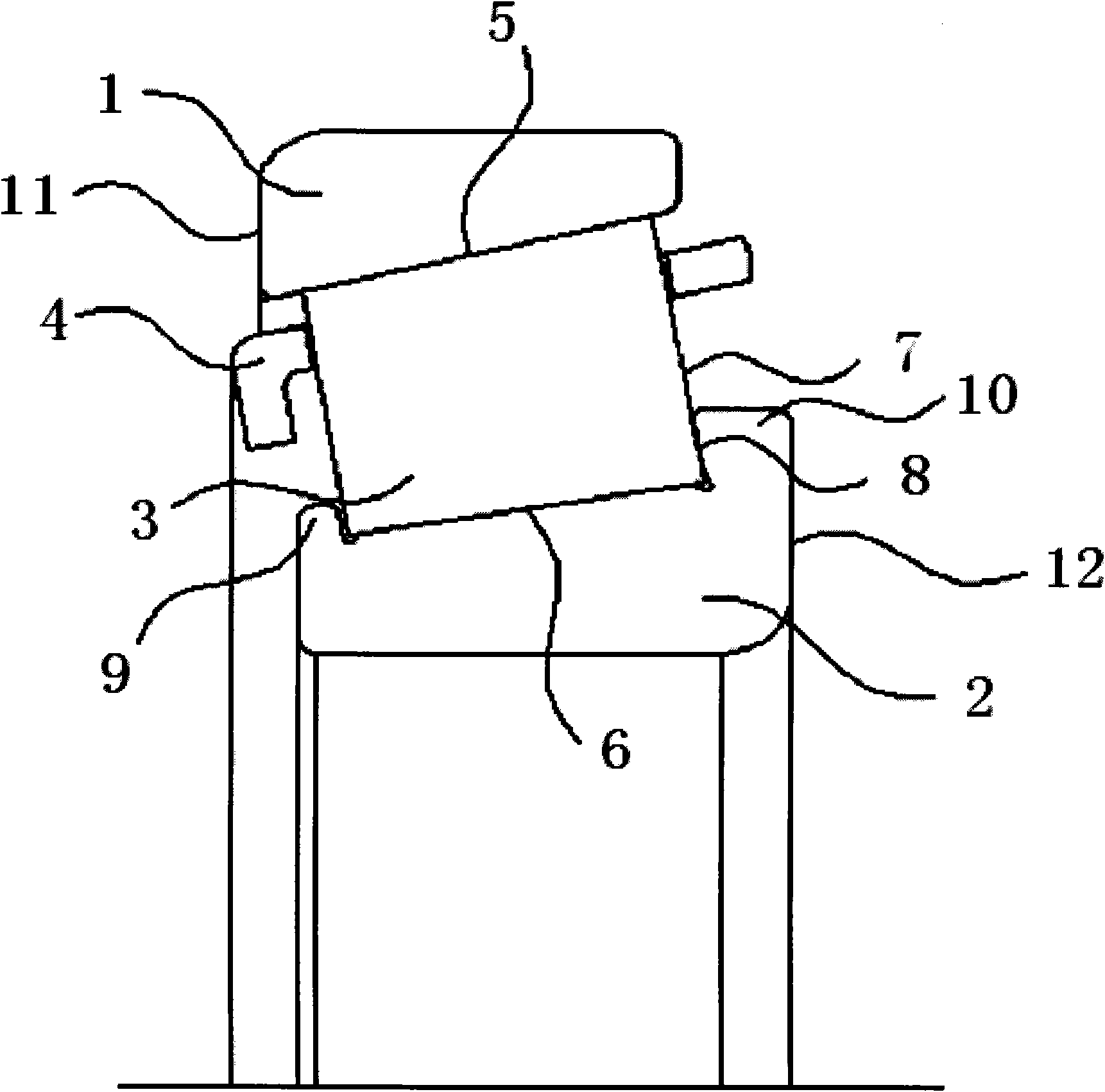
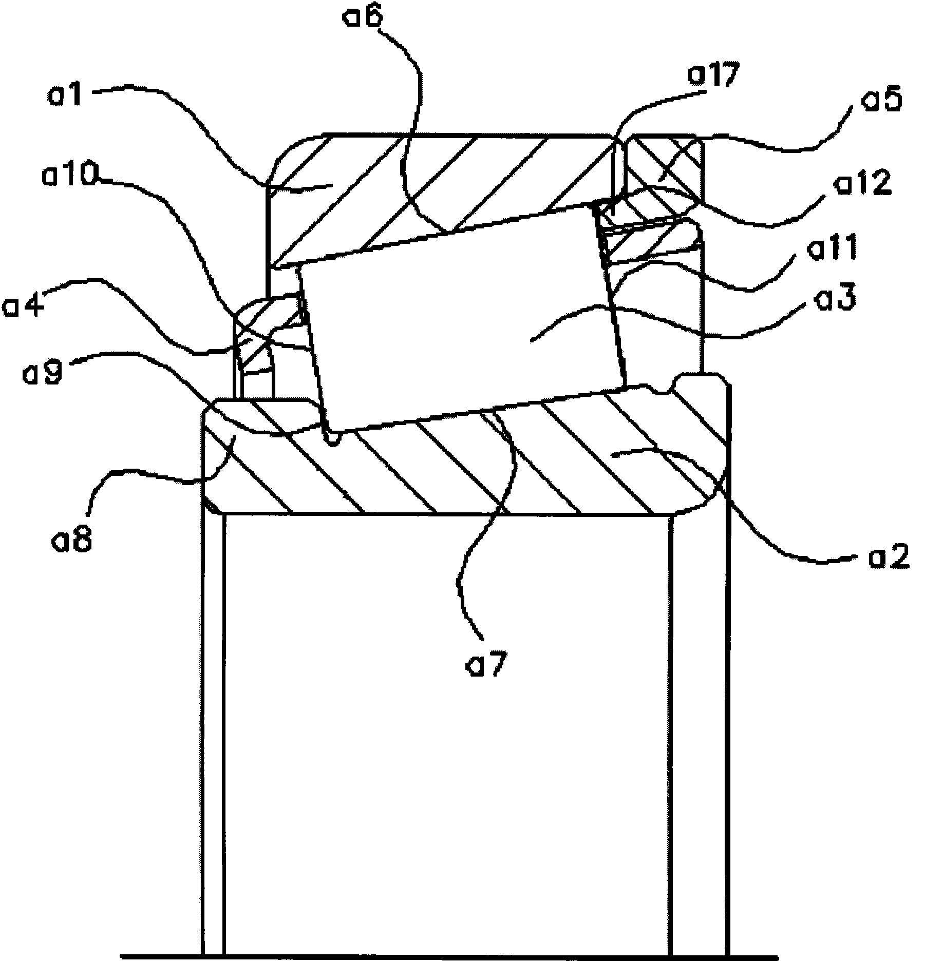
[0020] Such as figure 2 As shown, a tapered roller bearing includes an outer ring a1, an inner ring a2, a tapered roller a3 and a cage a4. The tapered roller a3 is arranged between the outer ring raceway a6 and the inner ring raceway a7, and the cage a4 It is installed at the large end face a11 and the small end face a10 of the tapered roller a3.

[0021] A flange portion a8 protruding from the inner ring raceway a7 is formed on the small-diameter end of the inner ring raceway a7, and a flange surface a9 is formed on the flange portion a8, and the flange surface a9 is in contact with the tapered roller. The small end face a10 of the child a3 is opposite, and the large diameter end of the inner ring raceway a7 does not protrude from the inner ring raceway a7.

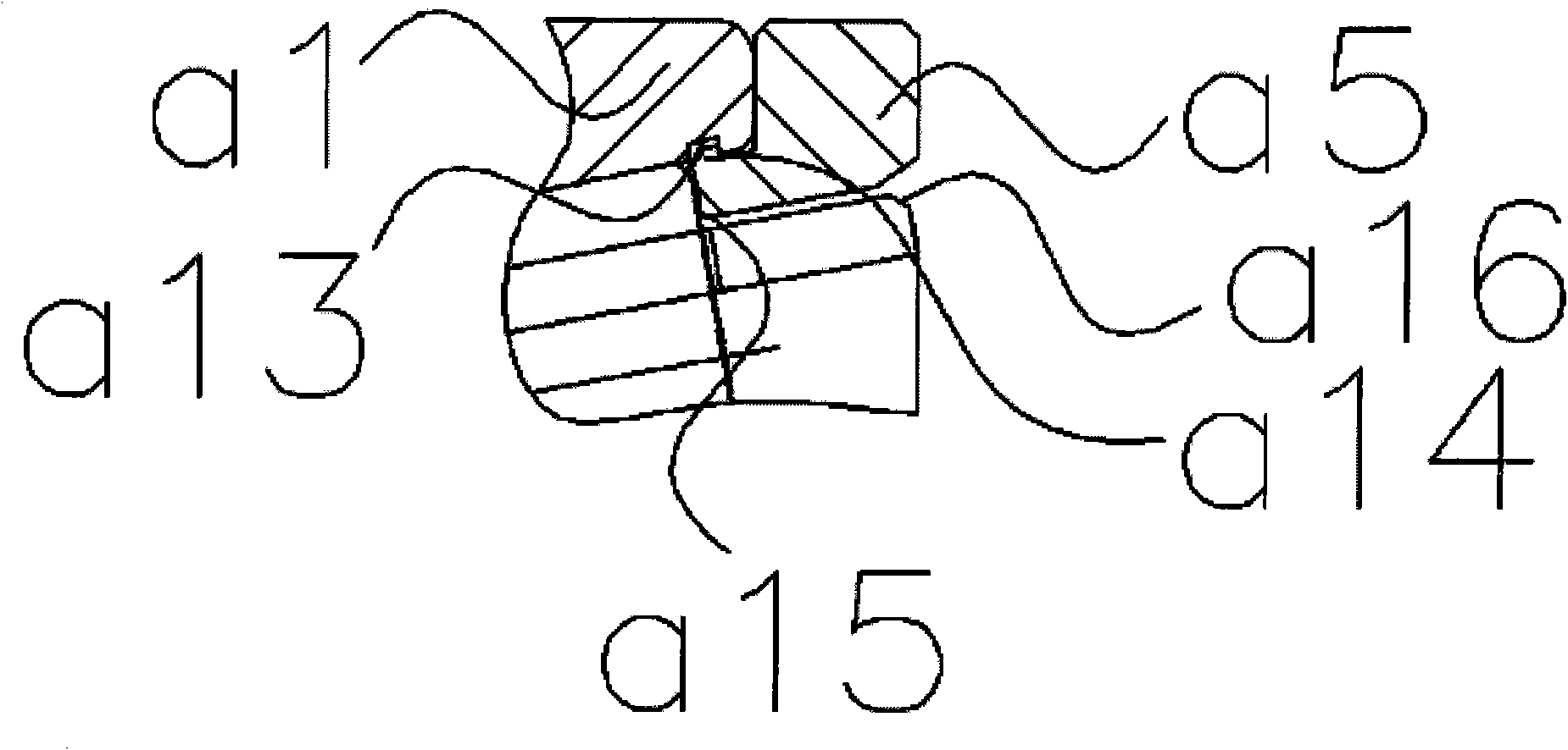
[0022] At the large-diameter end of the outer ring raceway a6, a floating retaining ring a5 is provided on the outer ring a1, and a protruding part protruding from the outer ring raceway a6 is formed on the floating re...


PUM


Abstract

The invention discloses a conical roller bearing. At the large-diameter end of an outer ring rollway of the conical roller bearing, a floating check ring is arranged on an outer ring, a flange protruding out of an inner ring rollway is formed on the small-diameter end of the inner ring rollway, and the large-diameter end of the inner ring rollway does not protrude out of the inner ring rollway; when the bearing is subjected to reversed axial force, the large end face of a conical roller contacts the floating check ring, the small end face of the conical roller contacts the flange on an inner ring, the reversed axial force is transferred by the flange on the inner ring, the conical roller and the floating check ring, the bearing is not released, so that one conical roller bearing can be subjected to two-way axial force; and the same effect can be achieved without using the two conical roller bearings, so the use of the conical roller bearing is prevented from being influenced due to the release of the conical roller bearing, and the space of installing the conical roller bearing is saved.

Description

technical field [0001] The invention relates to a bearing, in particular to a tapered roller bearing which can work normally under the action of bidirectional axial force. Background technique [0002] Tapered roller bearings are widely used in all kinds of machinery, especially in automobile axles and wheel hubs. Tapered roller bearings can bear combined radial and axial loads, and have a large bearing capacity. [0003] as attached figure 1 Shown is a schematic structural diagram of a tapered roller, which consists of an outer ring 1, an inner ring 2, a tapered roller 3 and a cage 4. The outer ring 1 has a tapered inner ring raceway 5, the inner ring 2 has a tapered outer ring raceway 6, and the two ends of the inner ring raceway have a small flange part 9 and a large flange part respectively. 10. The large end surface 7 of the tapered roller is a surface with a convex arc, and the surface 8 of the large flange part 10 of the inner ring is a surface with a concave arc. W...

Claims


Application Information

Patent Timeline
IPC IPC(8): F16C33/36F16C33/58
Inventor 屈平郭静瑜蔡旭东
Owner CSC BEARING
Why Eureka
Try Eureka