
Synchrotron radiation curve-edge focus lens design method by combining gravity bending coordinating and maximum application range

A technology with scope of application and design method, applied in the fields of synchrotron radiation beamline engineering and synchrotron radiation optics, it can solve the problems of not well eliminating the gravitational surface error and residual surface error, etc.

Inactive Publication Date: 2011-06-22
INST OF HIGH ENERGY PHYSICS CHINESE ACADEMY OF SCI
View PDF4 Cites 5 Cited by
  • Summary
  • Abstract
  • Description
  • Claims
  • Application Information

AI Technical Summary

Problems solved by technology

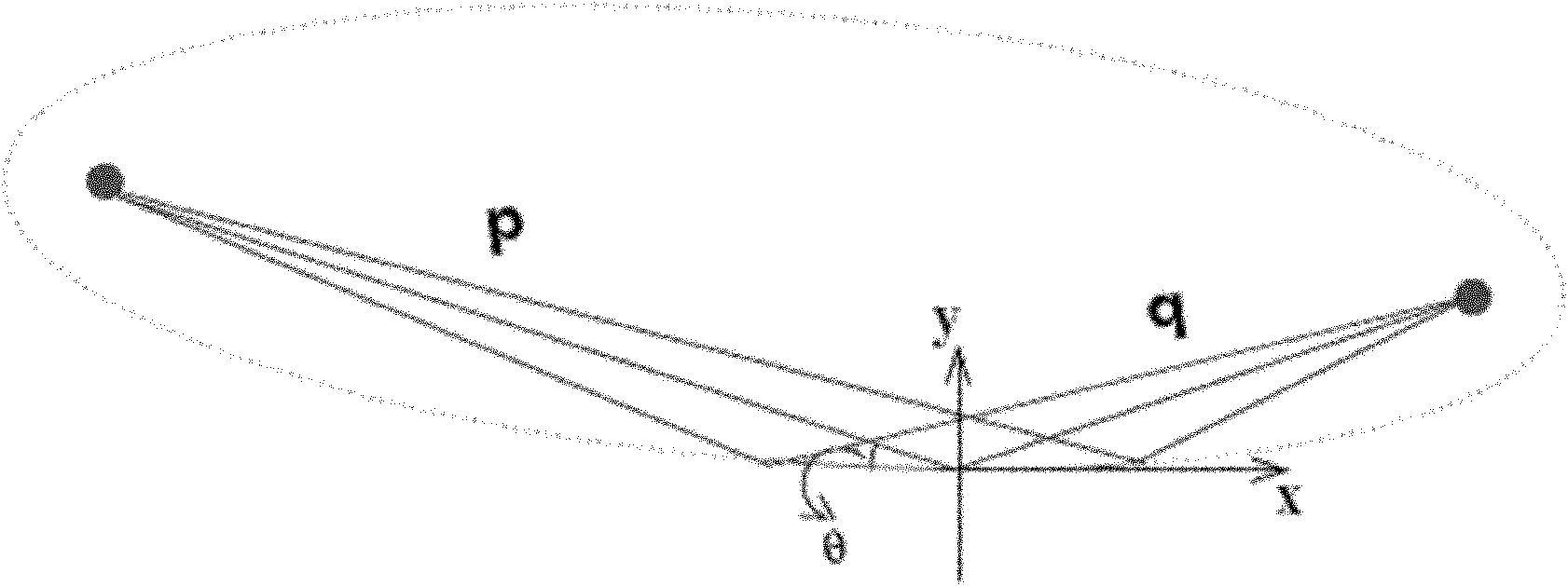
[0029] The purpose of the present invention is to provide a design method of gravity co-bending combined maximum application range of vertical focusing mirror with curved edge of synchrotron radiation, so as to solve the problem that the gravity surface shape error is not well eliminated in the prior art, and in the vicinity of the design focusing condition, the bending The error of the remaining surface shape after adjustment is very large, and there is no problem of maximizing the application range of the curved edge mirror

Method used


Image

  • Synchrotron radiation curve-edge focus lens design method by combining gravity bending coordinating and maximum application range
  • Synchrotron radiation curve-edge focus lens design method by combining gravity bending coordinating and maximum application range
  • Synchrotron radiation curve-edge focus lens design method by combining gravity bending coordinating and maximum application range

Examples


Embodiment Construction

[0060] The present invention will be described in further detail below in conjunction with the accompanying drawings and specific embodiments.

[0061] In the present invention, the design idea of ​​gravity-coordinated bending is not to use gravity as a system error source, but to incorporate it as a part of the bending force into the design of the bending surface together with the bending force applied at both ends, and design accordingly The geometric parameters and bending mechanical parameters of the mirror body, thereby eliminating the gravity surface shape error. The design idea of ​​maximizing the applicable range is to minimize the absolute value of the derivative of the root mean square of the total remaining surface shape error with respect to the focus condition at the design value, that is, the rise is the slowest near the design position as the focus condition changes, so that the Focusing mirrors maximize the range of application for a certain focusing condition....


PUM


Abstract

The invention provides a synchrotron radiation curve-edge vertical focus lens design method by combining gravity bending coordinating and the maximum application range. The method comprises the following steps of: establishing a gravity-containing bending deflection differential equation by taking the center of a lens body as an origin and an axis along the length of a lens surface as an x axis according to the beam bending theory of material mechanics; establishing a gravity bending coordinating design equation by making a bending surface have an oval shape; when a focusing condition deviation design value is calculated, adjusting a focus lens bending moment deviation design value to adapt to the variation of the focusing condition; establishing the maximum application range design equation by making residual surface shape slope error after the bending moment is adjusted increase at the lowest speed along with the focusing condition; and solving the bending mechanics and lens body geometric design parameter kMfd and W(x) functions by combining the gravity bending coordinating design equation and the maximum application range design equation. By the method, self-gravity surface shape error can be eliminated and the application range of the focusing condition is maximized.

Description

technical field [0001] The invention relates to a design method of a focusing mirror, in particular to a design method of a synchrotron radiation curvilinear vertical focusing mirror combined with gravity co-bending and a maximum applicable range which eliminates the surface shape error of self-gravity and realizes the maximum applicable range, and belongs to the synchrotron radiation beamline engineering, synchronous The field of radiation optics technology. Background technique [0002] One of the advantages of synchrotron radiation is its high brightness. Brightness generally refers to the photon number density in the phase space. The high photon flux of synchrotron radiation and the small volume of the phase space create the characteristics of high brightness. According to Liu Wei's theorem, the brightness cannot be increased without sacrificing the photon flux. When the line width of a beam is compressed, its angular width increases; conversely, when the angular width...

Claims


Application Information

Patent Timeline
IPC IPC(8): G02B19/00G02B5/10G02B27/00
Inventor 李明石泓盛伟繁刘鹏
Owner INST OF HIGH ENERGY PHYSICS CHINESE ACADEMY OF SCI
Learn More