Clamping method for shaft parts and holding device

A technology of clamping device and shaft parts, which is applied to machine tools designed for grinding the rotating surface of workpieces, grinding workpiece supports, grinding machines, etc. Low efficiency and other problems, to achieve the effect of simple and convenient installation, low cost, and improved work efficiency

Inactive Publication Date: 2011-06-29
梁美旭
View PDF0 Cites 10 Cited by
  • Summary
  • Abstract
  • Description
  • Claims
  • Application Information

AI Technical Summary

Problems solved by technology

[0002] In modern shaft grinding technology, there are many types of fixtures for clamping. When replacing different types of parts, it is often necessary to replace the corresponding special fixtures. The structure of various fixtures is complex and the cost is high. The shock resistance of various fixtures is not good. The positioning accuracy after installation is low. When the workpiece is long, it is necessary to install the center frame and fixture at the same time. The clamping and centering of the workpiece are complicated when installing the workpiece, and the center of the workpiece needs to be re-aligned after each clamping, and the work efficiency is low.

Method used


Image

  • Clamping method for shaft parts and holding device
  • Clamping method for shaft parts and holding device
  • Clamping method for shaft parts and holding device

Examples


Embodiment Construction

[0016] Specific embodiments of the present invention will be described in detail below in conjunction with the accompanying drawings.

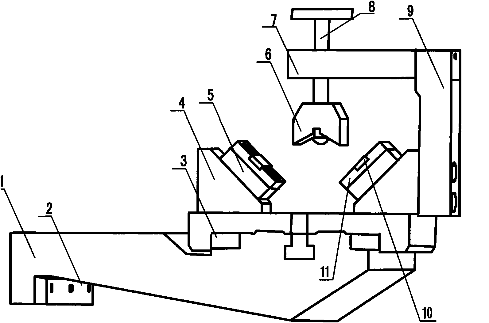
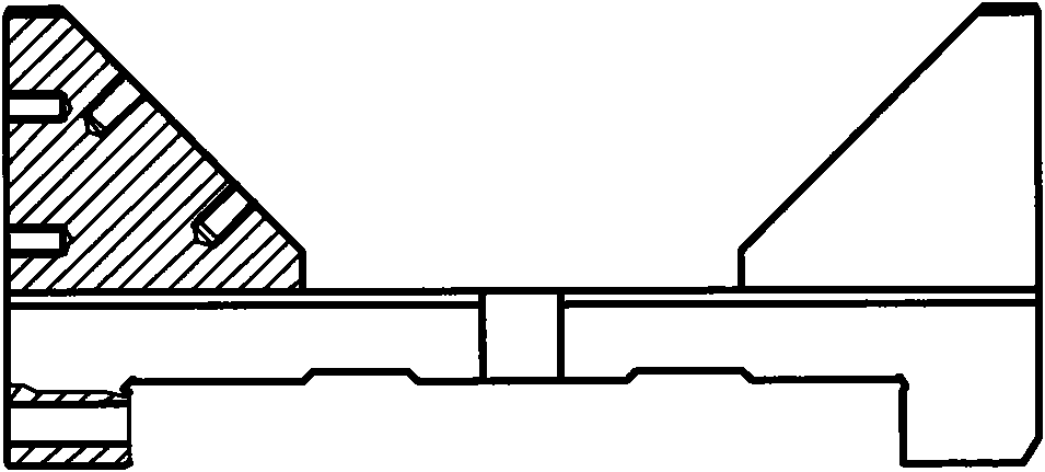
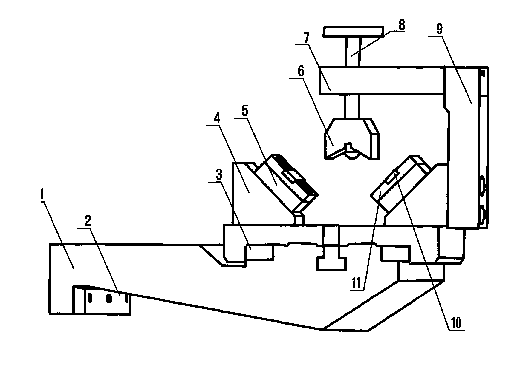
[0017] Such as Figure 1-Figure 2 As shown, the clamping method in the present invention is to place the workpiece on the small metal block 10 embedded in the center block 11 in the clamping device, and adjust the number and height of the small pads 5 to be consistent with the center height of the workpiece , to realize the radial positioning and centering of the workpiece, according to the size of the workpiece, the thread length of the adjusting bolt 8 can be adjusted until it is in close contact with the workpiece, and then tighten the screw hole on the fixing block 7 which is 90° from the hole in which the adjusting bolt 8 is installed The screw clamps and positions the workpiece axially and radially.

[0018] As shown in the figure, the clamping device of the present invention includes a clamp seat 1, an adjustment pad 2, a left and righ...


PUM


Abstract

A clamping method for shaft parts and a holding device belong to the technical field of grinding shafts. A conventional clamp has the disadvantages of smaller application range, complicated structure, higher cost, low positioning accuracy and low working efficiency. In the clamping method provided by the invention, radial positioning and centering of a workpiece can be achieved by adjusting the number and the heights of small cushion blocks, and the workpiece can be clamped and positioned in the axial direction and the radial direction by adjusting the length of screw threads of an adjusting bolt; the holding device of the invention also comprises a clamp seat, a big clamp block, a small clamp block, adjusting cushion blocks, center blocks and the like; the clamp seat is directly installed on a guide rail of a grinding machine; the two center blocks are arranged symmetrically and installed on two V-shaped surfaces of the big clamp block through the small cushion blocks; in addition, the big clamp block and the small clamp block are provided with V-shaped opening respectively, and are symmetrically arranged in the opposite directions. The clamping method and the holding device of the invention have the advantages of high positioning accuracy, simple operation, wide application range, low cost, high operating efficiency and the like, and the positioning accuracy can reach 0.001mm.

Description

technical field [0001] The invention belongs to the technical field of shaft grinding, and in particular relates to a grinding machine fixture. Background technique [0002] In modern shaft grinding technology, there are many types of fixtures for clamping. When replacing different types of parts, it is often necessary to replace the corresponding special fixtures. The structure of various fixtures is complex and the cost is high. The shock resistance of various fixtures is not good. The positioning accuracy after installation is low. When the workpiece is long, it is necessary to install the center frame and fixture at the same time. The clamping and centering of the workpiece are complicated when installing the workpiece, and the center of the workpiece needs to be re-aligned after each clamping, and the work efficiency is low. Contents of the invention [0003] The purpose of the present invention is to overcome various shortcomings of the existing fixtures, and provide...

Claims


Application Information

Patent Timeline
Patent Type & Authority Applications(China)
IPC IPC(8): B24B5/22B24B41/06
Inventor 梁美旭
Owner 梁美旭
Why Eureka
Try Eureka