Pad cover fastening structure

A pad cover, airbag technology, applied in the direction of vehicle safety arrangement, pedestrian/occupant safety arrangement, transportation and packaging, etc., can solve the problem of not easy to eliminate the gap and so on

Active Publication Date: 2011-06-29
TOYODA GOSEI CO LTD
View PDF6 Cites 4 Cited by
  • Summary
  • Abstract
  • Description
  • Claims
  • Application Information

AI Technical Summary

Problems solved by technology

[0009] However, in the fastening structure for the backing plate cover according to the above disclosure, when the fastening member 96 is bent and a part of each supporting portion 97 is ...

Method used


Image

  • Pad cover fastening structure
  • Pad cover fastening structure
  • Pad cover fastening structure

Examples


Embodiment Construction

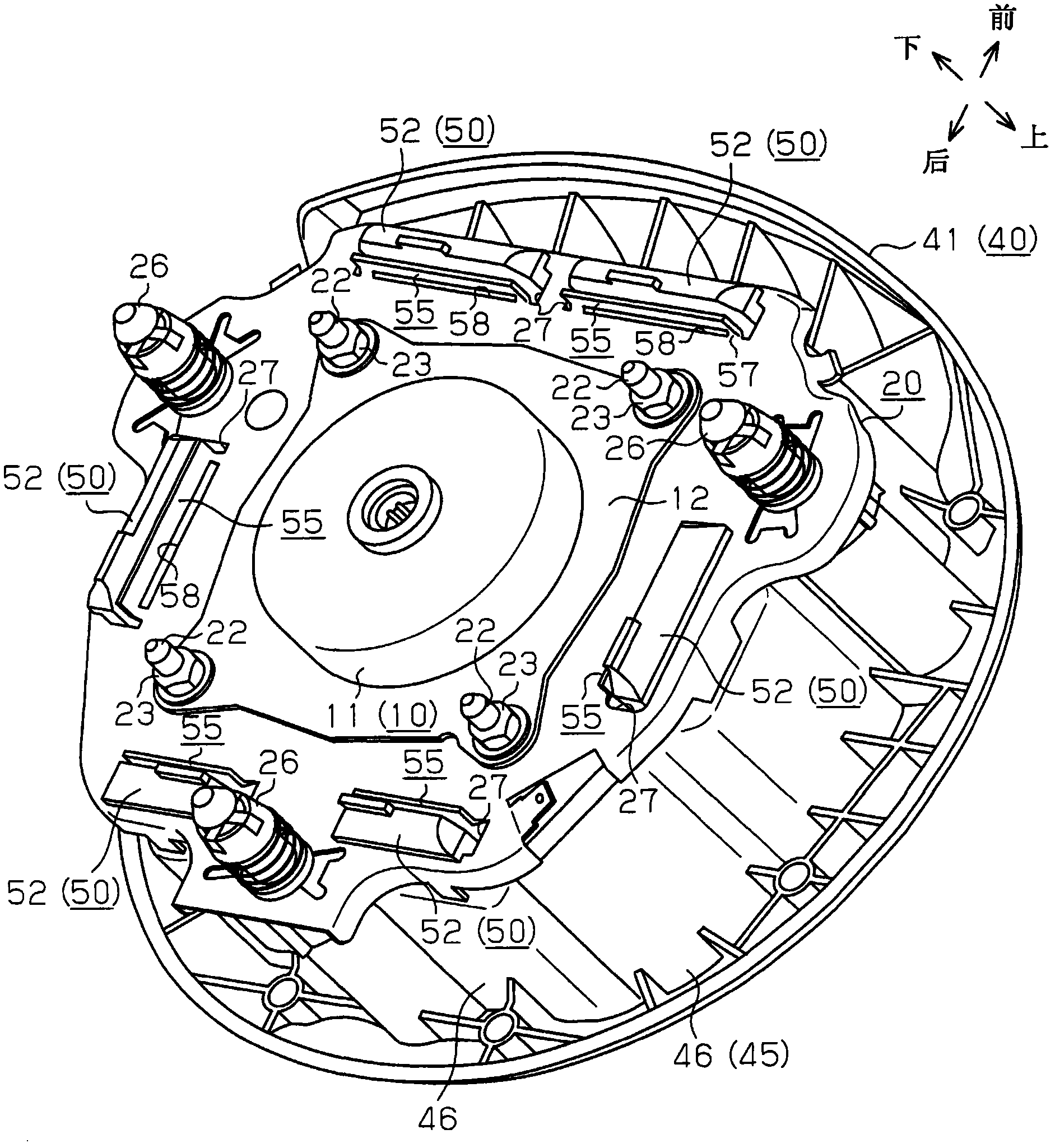
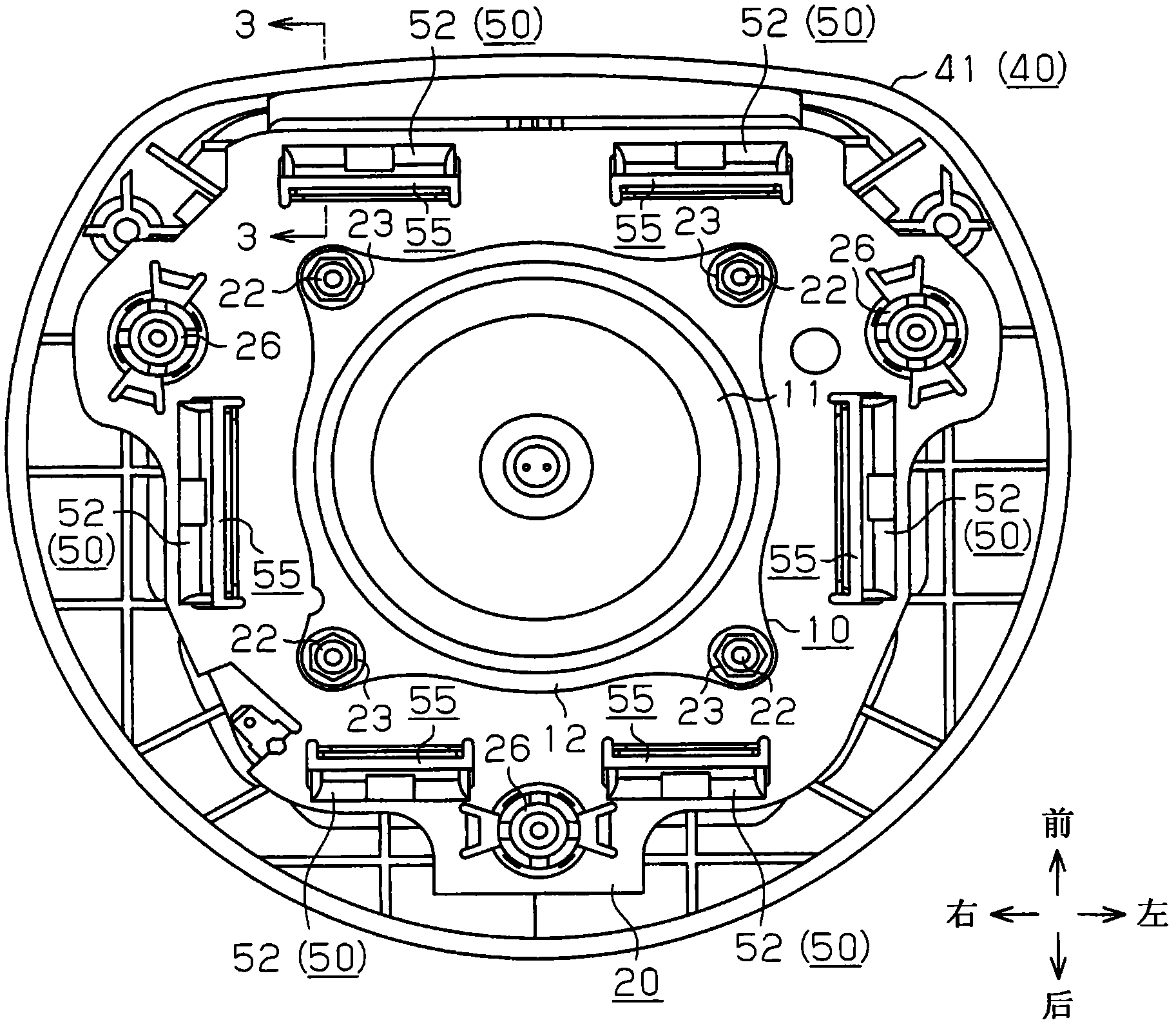
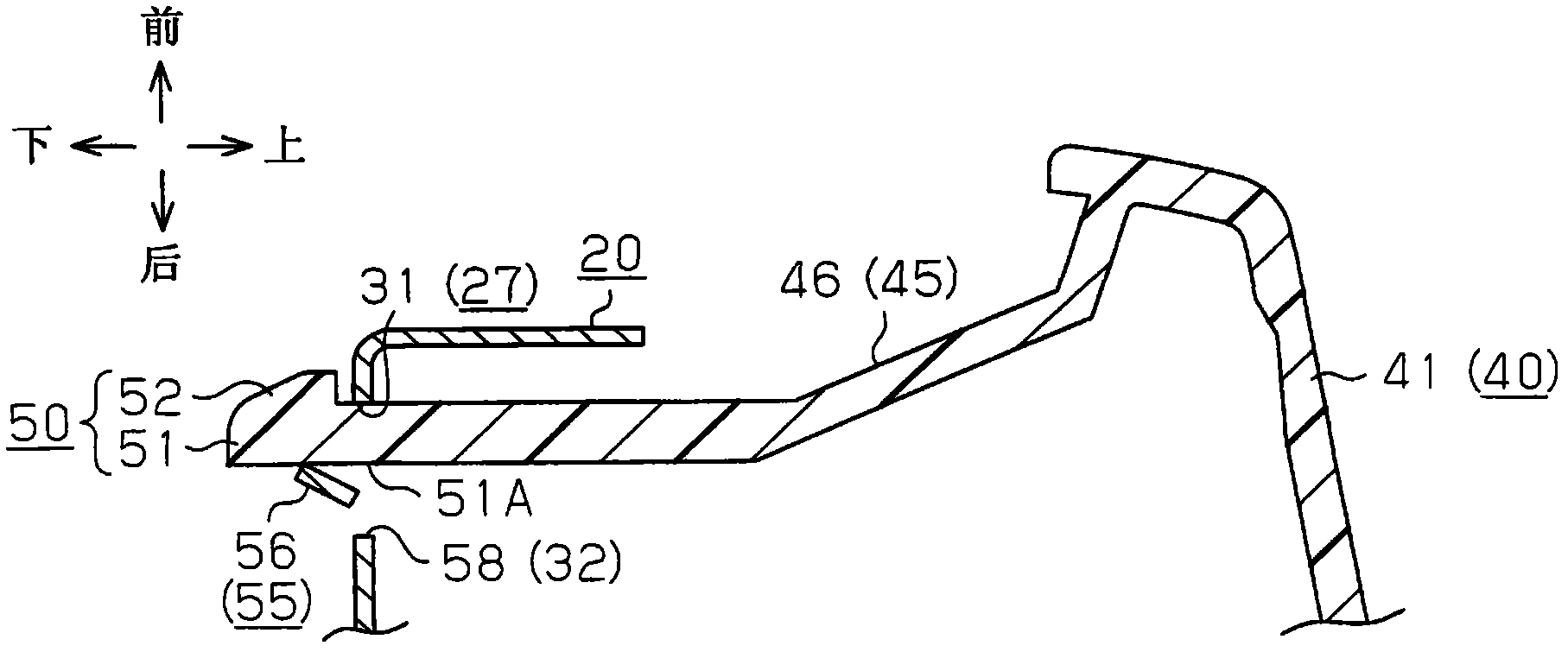
[0032] The following will refer to Figure 1 to Figure 1 4. Describe the fastening structure of the base plate cover according to one embodiment of the present invention.

[0033] Such as figure 1 and figure 2 As shown, the steering wheel with the airbag device 10 includes a bag holder 20 and a pad cover 40 . The airbag device 10 is fastened to the pad cover 40 through the bag holder 20 .

[0034] The airbag device 10 has an airbag (not shown) and an inflator 11 . The airbag is formed from a bag-shaped piece of woven cloth. The airbag is of such a size that it can inflate and deploy between the steering wheel and the driver. Folding the airbag in such a way that the airbag can be inflated and deployed gives the airbag a compact form. The airbag has an opening at its lower end through which the inflation gas from the inflator 11 flows.

[0035] The inflator 11 is in the form of a cylinder with a small height. The inflator 11 accommodates a gas generating agent (not sh...


PUM


Abstract

The present invention discloses a pad cover fastening structure. A bag holder has a plurality of engagement holes about parts to which an airbag device is attached. Each engagement hole has a first long inner wall surface and a second long inner wall surface that extend along a substantially tangential direction of the center a circle of which coincides with the central axis of the bag holder, orof an opening. Engagement claws of a pad cover each include an insertion portion inserted into one of the engagement holes and a claw portion protruding from the lower end of the insertion portion toward the first long inner wall surface. The bag holder has integrally formed fastening pieces, each of which includes a support portion and a pair of coupling portions. The support portion is located in the vicinity of one of the engagement holes, and the coupling portions connect the support portion to the corresponding second long inner wall surface at several positions. Each fastening piece is bent at the coupling portions so as to contact a side surface of the insertion portion on which no claw portion is provided.

Description

technical field [0001] The present invention relates to a structure for fastening a pad cover to a bag holder in a steering wheel having an airbag device. Background technique [0002] For example, Korean Patent Application Publication No. 10-2009-0026529 discloses a fastening structure for a backing plate cover. now refer to Figure 15 to Figure 17 This fastening structure will be described. The steering wheel with the airbag device 80 has a bag holder 70 and a pad cover 90 in addition to the airbag device 80 . [0003] The bag holder 70 is formed of a pressed metal plate, and is arranged under the airbag device. The airbag device 80 is fixed to the bag holder 70 by bolts 81 and nuts 82 (see attached Figure 16 ). The bag holder 70 has a plurality of engaging holes 71 each located near a portion where the airbag device 80 is mounted, that is, near the bolt 81 and the nut 82 . Each engagement hole 71 extends substantially linearly along a tangential direction of a circl...

Claims


Application Information

Patent Timeline
IPC IPC(8): B60R21/215B60R21/203
CPCB60R21/2037B60R21/215B60R2021/21543
Inventor 饭田仁广濑修屉木健治
Owner TOYODA GOSEI CO LTD
Why Eureka
Try Eureka