Drum motor stator structure

A technology of stator structure and roller motor, which is applied in the direction of magnetic circuit shape/style/structure, magnetic circuit static parts, etc., can solve the problems such as difficulty in meeting the expansion requirements of the roller motor, small stator slot volume, and low motor work efficiency, etc. Achieve the effect of saving materials, low development cost and improving work efficiency

Active Publication Date: 2011-06-29
ZHONGSHAN BROAD OCEAN
View PDF6 Cites 24 Cited by
  • Summary
  • Abstract
  • Description
  • Claims
  • Application Information

AI Technical Summary

Problems solved by technology

[0002] At present, the vast majority of drum motors adopt a conventional full-circle stator structure. Through the interference fit between the outer wall of the full-circle stator core and the inner wall of the drum shell, the full-circle stator and the drum shell are connected together. This structure is adopted , there are the following problems: 1) The volume of the stator slot of the full-circle stator is not large. Due to the limited volume of the stator slot, the slot fullness rate of the stator coil windings wound in the stator slot is low, resulting in low working efficiency of the motor. Poor performance; 2) For full-circle stators with different varieties and specifications, the overall mold opening mold uses more materials, and it is necessary to develop production molds of different specifications. The versatility is not strong, the development cost is high, and it is difficult to meet different varieties, Expansion requirements for different power drum motors

Method used


Image

  • Drum motor stator structure
  • Drum motor stator structure
  • Drum motor stator structure

Examples


Embodiment Construction

[0026] The present invention will be described in further detail below through specific embodiments and in conjunction with the accompanying drawings.

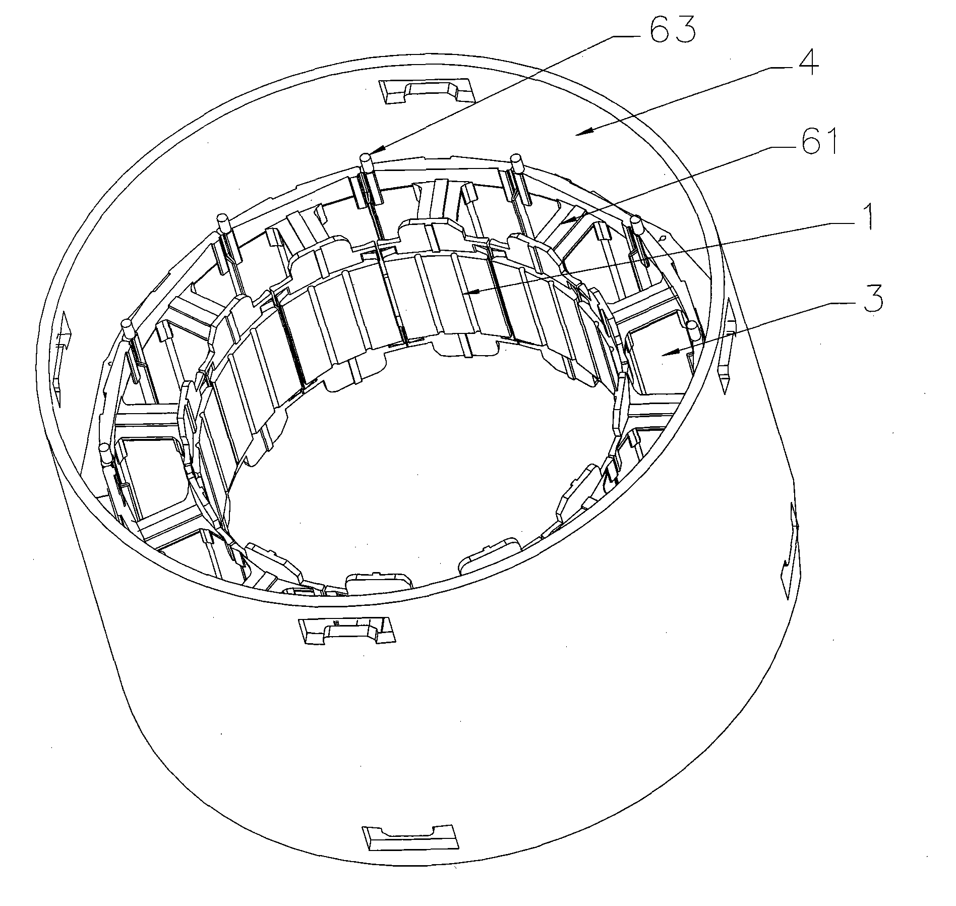
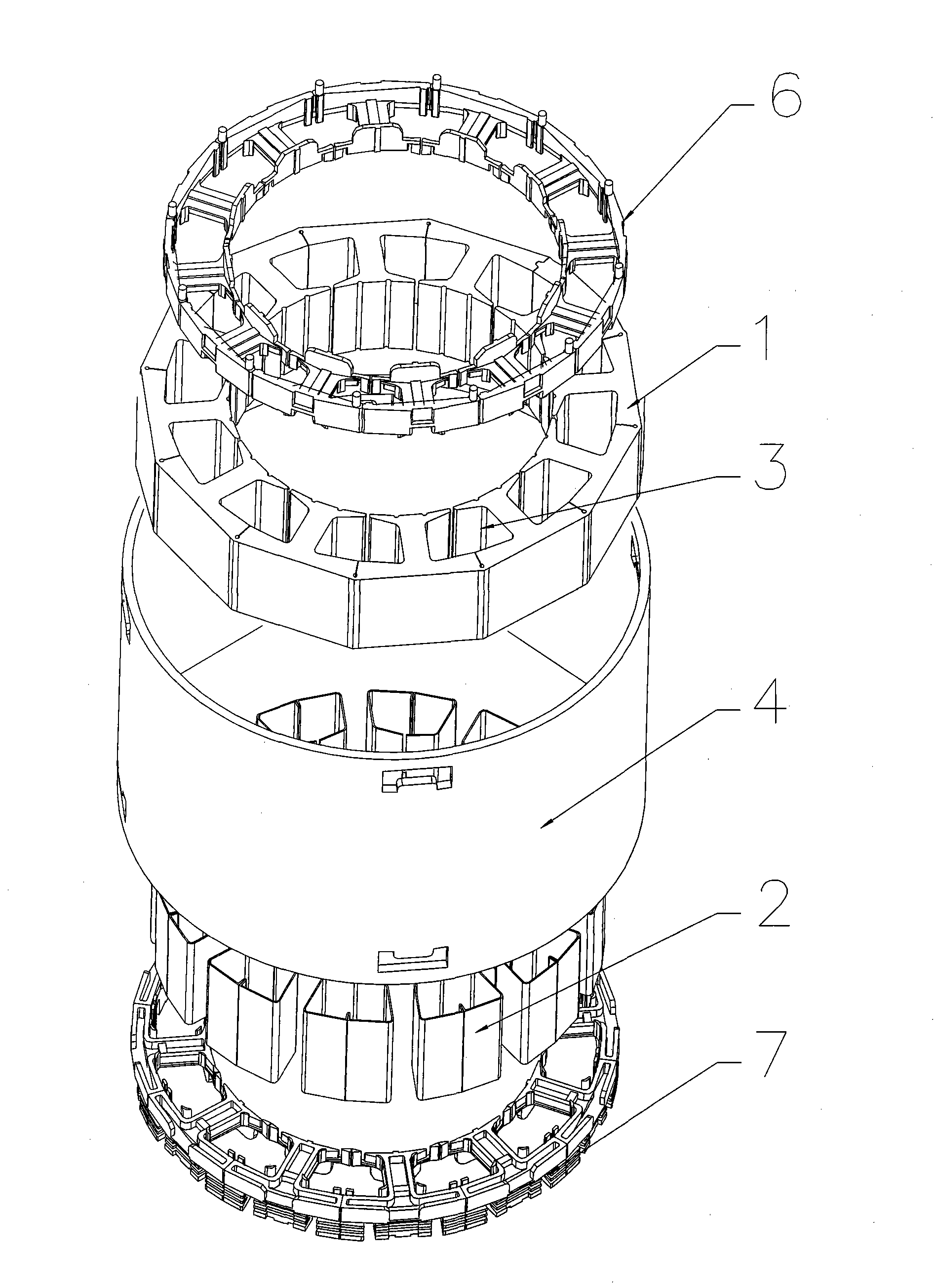
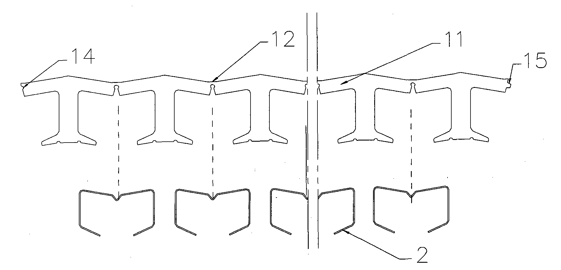
[0027] Depend on Figure 1 to Figure 5 It can be seen that a drum motor stator structure includes a stator core 1, end insulation, stator slot paper 2 and stator coil windings, the stator slot paper 2 is installed in the stator slot 3 of the stator core 1, and the end insulation is arranged on On both ends of the stator core 1, the stator coil windings are wound on the end insulation, and a drum casing 4 is installed on the outer edge of the stator core 1. The stator core adopts a strip-shaped stator core, and the strip-shaped stator iron The core 1 is bent into an annular shape and installed inside the drum casing 4, and the outer wall of the annular strip-shaped stator core is in interference fit with the inner wall of the drum casing.

[0028] Among them, the ring-shaped strip stator core 1 and the drum casing 4 are closel...


PUM


Abstract

The invention discloses a drum motor stator structure. The drum motor stator structure comprises a stator core, end insulation, stator slot paper and stator coil windings, wherein the stator slot paper is arranged in a stator slot of the stator core; the end insulation is arranged on the two end surfaces of the stator core; the stator coil windings are wound on the end insulation; a drum shell is arranged on the outer edge of the stator core; the stator core adopts a stripped stator core; the stripped stator core is bent to be annular and is arranged in the drum shell; and the outer wall of the annular stripped stator core and the inner wall of the drum shell are in interference fit. In the drum motor stator structure, the stripped stator core structure is adopted; and in the state of naturally unfolding the stripped stator core structure, the volumes of the coil windings in the stator slot are increased, the slot fullness rate is improved, the work efficiency of the motor is greatly improved, and the motor performance is very high.

Description

Technical field: [0001] The invention relates to a drum motor stator structure. Background technique: [0002] At present, the vast majority of drum motors adopt a conventional full-circle stator structure. Through the interference fit between the outer wall of the full-circle stator core and the inner wall of the drum shell, the full-circle stator and the drum shell are connected together. This structure is adopted , there are the following problems: 1) The volume of the stator slot of the full-circle stator is not large. Due to the limited volume of the stator slot, the slot fullness rate of the stator coil windings wound in the stator slot is low, resulting in low working efficiency of the motor. Poor performance; 2) For full-circle stators with different varieties and specifications, the overall mold opening mold uses more materials, and it is necessary to develop production molds of different specifications. The versatility is not strong, the development cost is high, a...

Claims


Application Information

Patent Timeline
Patent Type & Authority Applications(China)
IPC IPC(8): H02K1/12H02K1/14H02K1/16
Inventor 张旭
Owner ZHONGSHAN BROAD OCEAN
Why Eureka
Try Eureka