Supercharge Your Innovation With Domain-Expert AI Agents!

Connector

A connector and connecting arm technology, which is applied in the direction of connection, fixed connection, and parts of the connecting device, can solve the problems of reduced life of the elastic arm 11', poor high-frequency connection characteristics of the connector, and large internal stress, etc., to avoid Effect of high-frequency interference, high-performance high-frequency connection characteristics

Active Publication Date: 2011-07-06
SUNWAY COMM JIANGSU CO LTD
View PDF5 Cites 9 Cited by
  • Summary
  • Abstract
  • Description
  • Claims
  • Application Information

AI Technical Summary

Problems solved by technology

[0003] For the above-mentioned traditional connector, first, there is only one communication path formed by the elastic arm 11' and it is the only communication path, and the high-frequency current can only flow between the electronic component and the circuit board through this only communication path, therefore, The connector has poor high-frequency connection characteristics
Second, the contact reliability between the electronic component and the elastic arm 11' is only maintained by the elastic force of one elastic arm 11', so the deformation of the elastic arm 11' is large, the internal stress is large, and the size of the elastic force is limited, which reduces the connection. reliability, and the lifetime of the elastic arm 11' is reduced
Third, when the electronic component presses down on the elastic arm 11', if it is over-compressed downward, the elastic arm 11' may come into contact with the circuit board, thereby causing short circuit and other faults to occur. In addition, if the elastic arm 11' is pressed down Excessive, it is possible to permanently deform the elastic arm 11', that is, when the electronic component is removed, the elastic arm 11' cannot be restored, so that when the electronic component is connected again, the elastic arm 11' loses its upward elastic force, which affects the connection between the electronic component and the elastic arm. Contact reliability between 11'
Fourth, when the elastic arm 11' is compressed downward, the elastic arm 11' exists in Image 6 The possibility of movement in the front and rear direction of the medium, so that the elastic arm 11' will generate torsion force, which may damage the connection between the main body 10' and the circuit board

Method used


Image

  • Connector
  • Connector
  • Connector

Examples


Embodiment Construction

[0035] Embodiments of the present invention are described in detail below, examples of which are shown in the drawings, wherein the same or similar reference numerals designate the same or similar elements or elements having the same or similar functions throughout. The embodiments described below by referring to the figures are exemplary only for explaining the present invention and should not be construed as limiting the present invention.

[0036] In the description of the present invention, the orientation or positional relationship indicated by the terms "longitudinal", "transverse", "upward", "downward", etc. are based on the orientation or positional relationship shown in the drawings, and are only for the convenience of describing the present invention It is not intended that the invention must be constructed and operated in a particular orientation, and thus should not be construed as limiting the invention.

[0037] A connector according to an embodiment of the prese...


PUM


Abstract

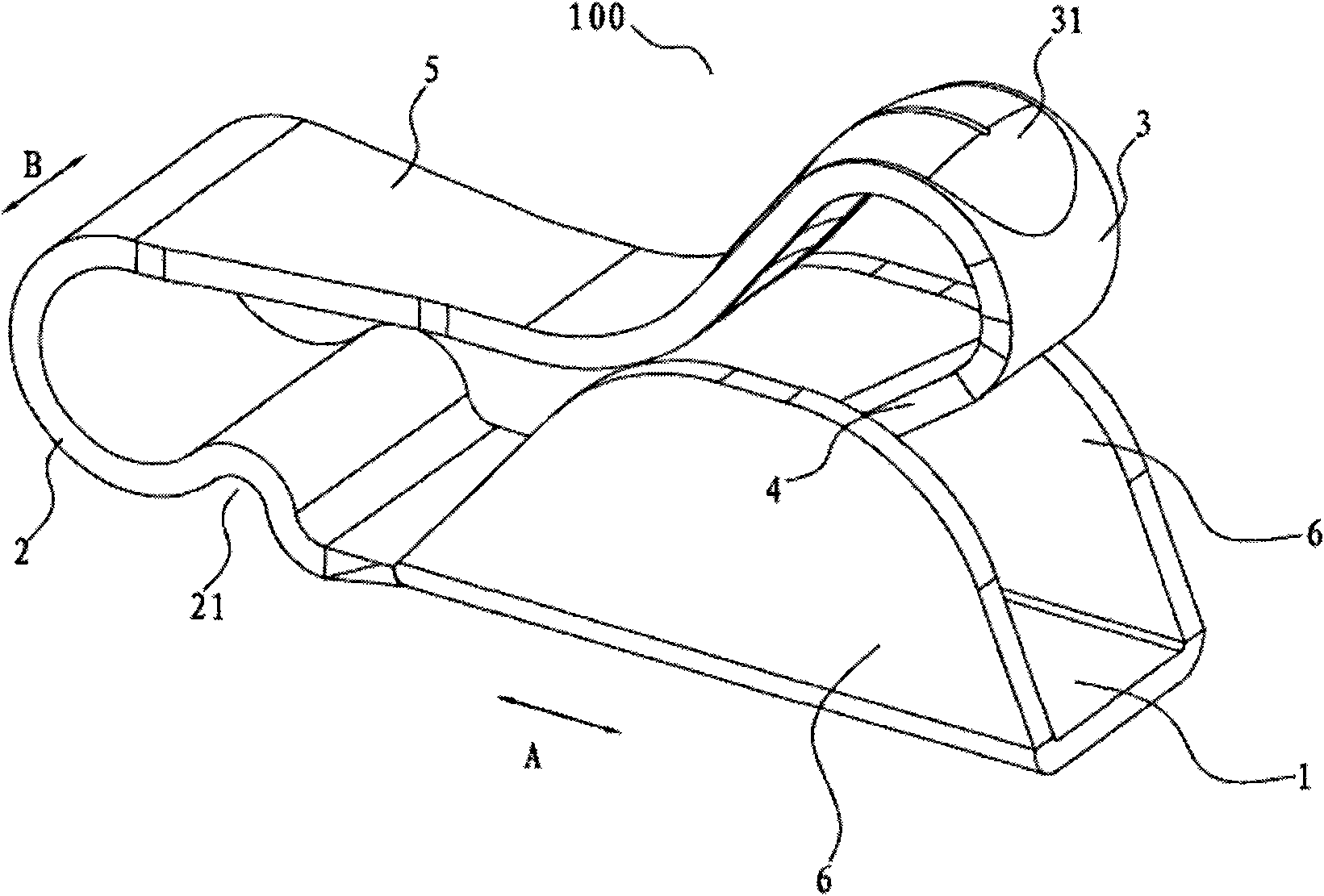
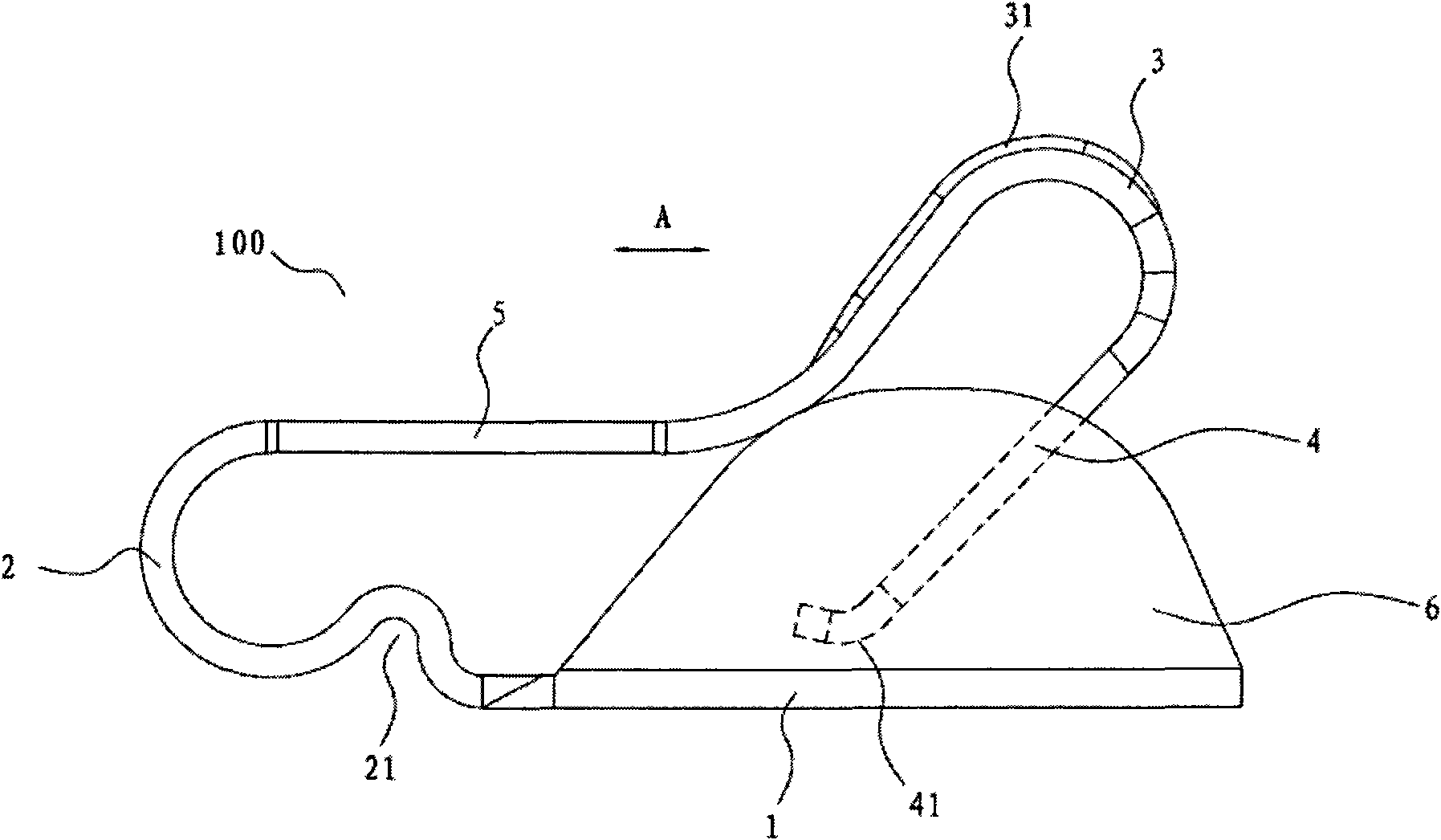
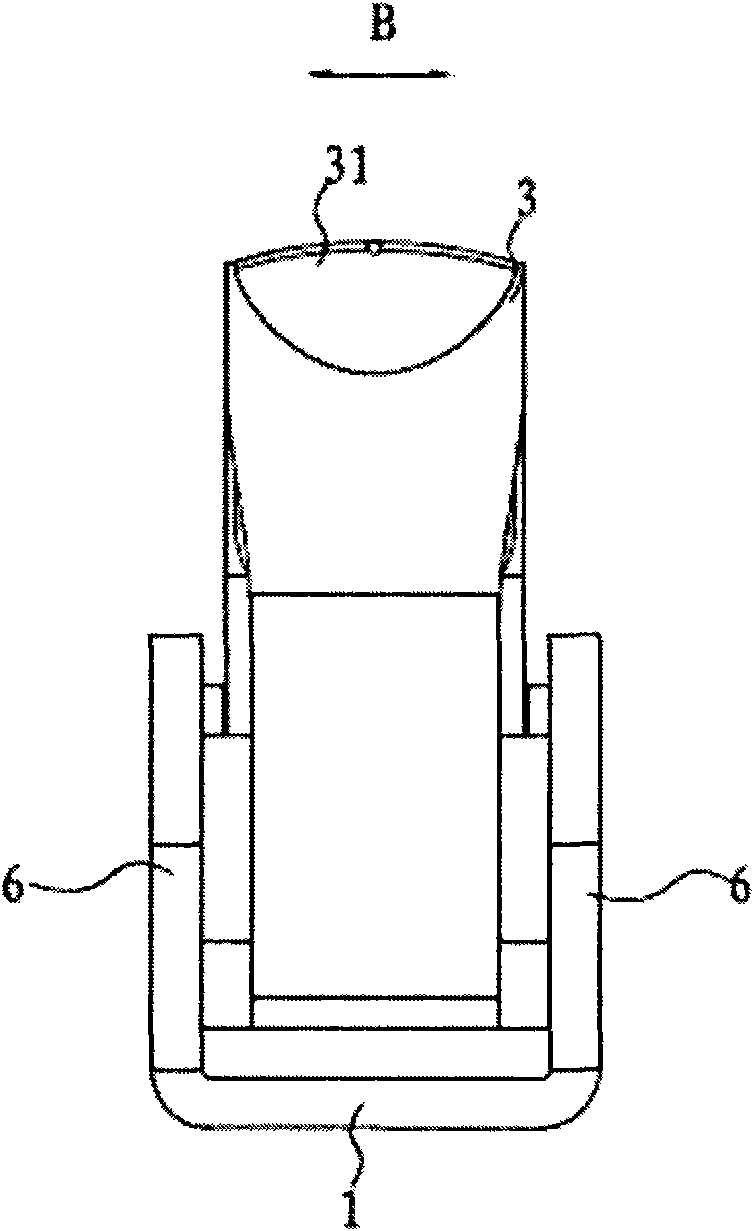
The invention discloses a connector comprising a welding plate, a first connecting arm, a contact arm and a second connecting arm, wherein the welding plate is provided with a first end and a second end along the longitudinal direction; the first end of the first connecting arm is connected with the second end of the welding plate, and the second end of the first connecting arm extends upwards relative to the first end of the first connecting arm; the first end of the contact arm is connected with the second end of the first connecting arm; and the first end of the second connecting arm is connected with the second end of the contact arm, and the second end of the second connecting arm extends downwards towards the welding plate and can be in contact with the welding plate. The connector disclosed by the invention has a plurality of connected passages, and high-frequency current can flow along the passage with minimum resistance, thereby realizing a high-performance high-frequency connection characteristic, and avoiding high-frequency interference.

Description

technical field [0001] The invention relates to a connector, in particular to a multi-channel electrical connector. Background technique [0002] Electrical connectors have a wide variety of uses, such as are commonly used to connect electronic components to circuit boards. Traditional electrical connectors such as Image 6 As shown, it includes a sheet-shaped body 10' and an elastic arm 11' protruding upward from one end of the body 10'. One end of the elastic arm 11' is connected to the body 10' and the free end is generally arc-shaped. When in use, the body 10' is soldered to the circuit board (PCB), the electronic component is in contact with the elastic arm 11' and presses down the elastic arm 11', thereby connecting the electronic component with the circuit board, and relying on the upward elastic force of the elastic arm 11' The contact reliability between the elastic arm 11' and the electronic component is ensured. [0003] For the above-mentioned traditional conne...

Claims


Application Information

Patent Timeline
Patent Type & Authority Applications(China)
IPC IPC(8): H01R12/55H01R12/57H01R13/24
CPCH01R13/2407H01R12/57H01R12/51H01R13/24
Inventor 于伟张海军
Owner SUNWAY COMM JIANGSU CO LTD
Features
  • R&D
  • Intellectual Property
  • Life Sciences
  • Materials
  • Tech Scout
  • Unparalleled Data Quality
  • Higher Quality Content
  • 60% Fewer Hallucinations
Learn More