Driving circuit for input/output port

A driving circuit and main output technology, applied in the direction of logic circuit connection/interface arrangement, logic circuit coupling/interface using field effect transistors, etc., can solve the problems of reducing the output signal speed, affecting the processing speed of integrated circuits, etc., to improve the speed Effect

Active Publication Date: 2011-07-06
PHISON ELECTRONICS
View PDF0 Cites 1 Cited by
  • Summary
  • Abstract
  • Description
  • Claims
  • Application Information

AI Technical Summary

Problems solved by technology

However, due to such a solution (solution), it is very likely that the speed of the output signal will be reduced a lot, so that the overall processing speed of the integrated circuit will be affected.

Method used


Image

  • Driving circuit for input/output port
  • Driving circuit for input/output port
  • Driving circuit for input/output port

Examples


Embodiment Construction

[0029] The foregoing and other technical contents, features and effects of the present invention will be clearly presented in the following detailed descriptions of multiple embodiments with reference to the drawings. Additionally, reference will now be made in detail to embodiments of the present invention, examples of which are illustrated in the accompanying drawings. Furthermore, wherever possible, elements / members using the same reference numerals in the drawings and embodiments represent the same or similar parts.

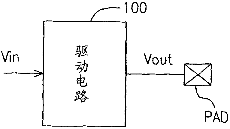
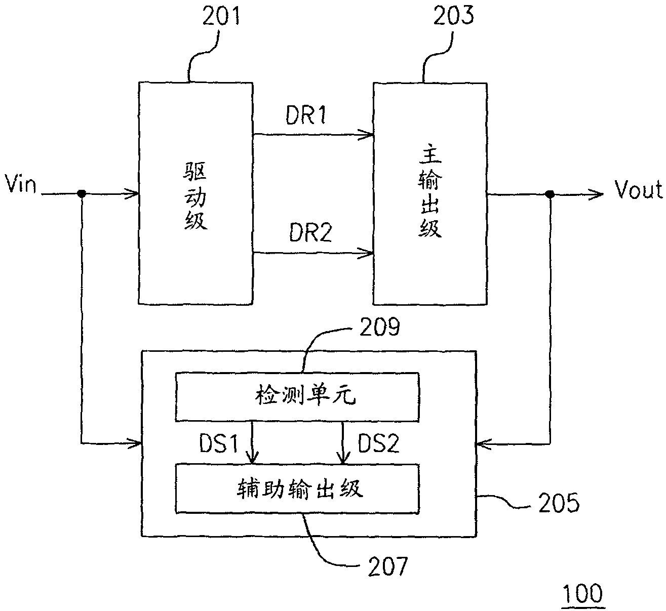
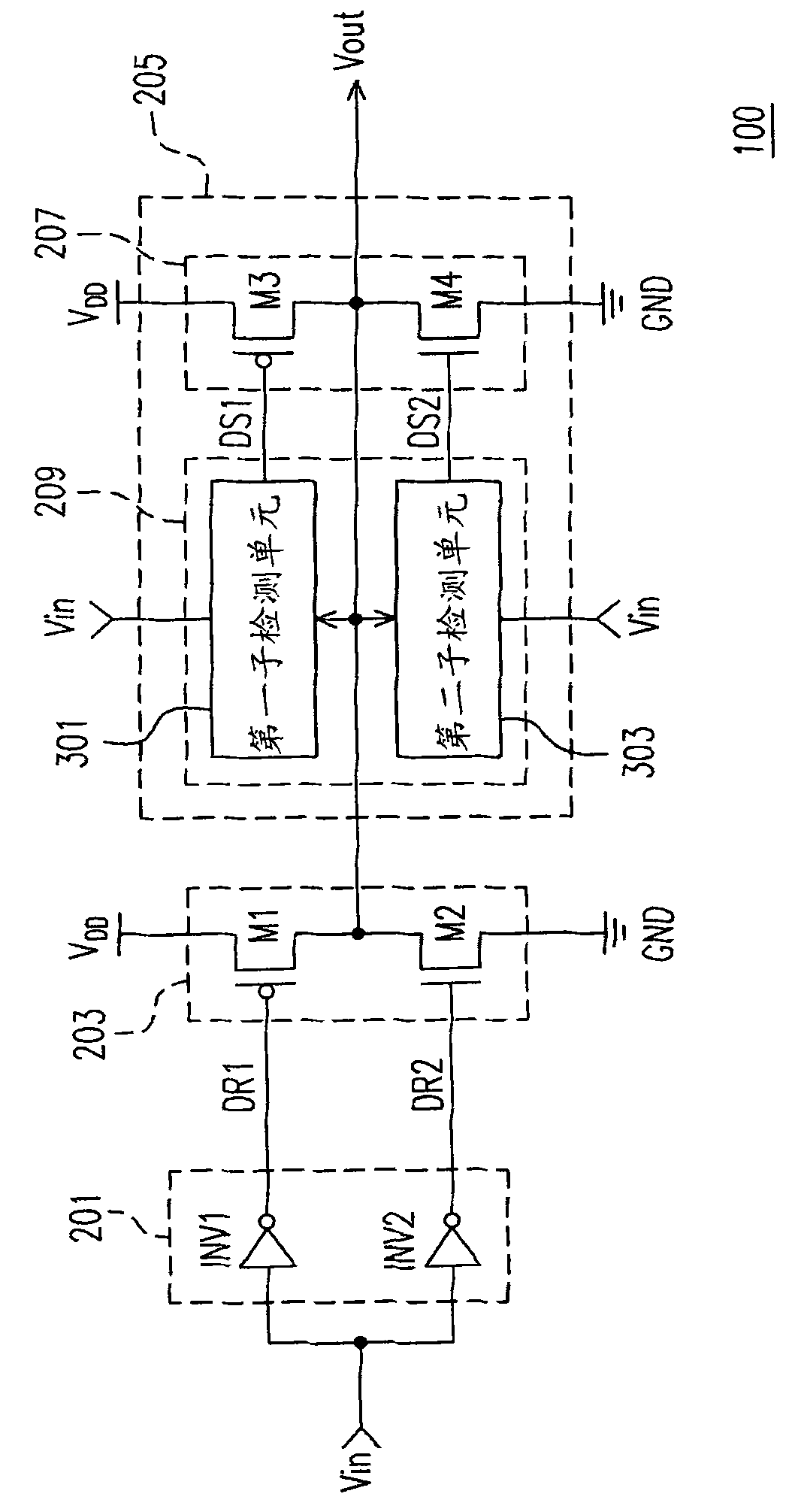
[0030] figure 1 It is a schematic diagram of a driving circuit 100 according to an embodiment of the present invention. figure 2 Shown is a block diagram of a driving circuit 100 according to an embodiment of the present invention. Please merge reference figure 1 and figure 2 , the driving circuit 100 can be, for example, a digital input / output interface (digital I / O interface), which is used to receive the input signal Vin generated by, for example, ...


PUM


Abstract

The invention provides a driving circuit for an input / output port, which comprises a main output stage and an enhancing unit, wherein the main output stage is used for receiving at least one driving signal and outputting an output signal corresponding to an input signal based on the driving signal, and the enhancing unit is coupled with the main output stage and is used for receiving and detecting the electrical level of the output signal, thereby maintaining or enhancing the output thrust of the main output stage.

Description

technical field [0001] The present invention relates to a driving circuit, and in particular to a driving circuit of an input / output interface. Background technique [0002] Generally speaking, when a digital signal is transmitted through a driving circuit (that is, an input / output interface (I / O)) in an integrated circuit (IC), in order to increase the transmission speed, the driving of the driving circuit must be increased. capacity (that is, the output thrust of I / O), but in the case of increasing the driving capacity, it is bound to face the situation of over damping of the output signal, such as Image 6 as shown. Such jitter will not only become power noise to interfere with the system power supply, but will also be emitted in the form of electromagnetic disturbance (EMI), resulting in product specifications not meeting safety standards. [0003] Traditionally, the problem of overshoot jitter caused by the increase of the driving capability of the output signal can be...

Claims


Application Information

Patent Timeline
Patent Type & Authority Applications(China)
IPC IPC(8): H03K19/0185
Inventor 林谕栋刘育嘉李建纬
Owner PHISON ELECTRONICS
Why Eureka
Try Eureka