Load sharing method and equipment for stacked ring topology

A ring topology and load sharing technology, applied in the stacking field, can solve the problems of link bandwidth waste, bandwidth waste, unfavorable load sharing, etc., and achieve the effect of improving bandwidth utilization and realizing load sharing

Active Publication Date: 2011-07-06
NEW H3C TECH CO LTD
View PDF9 Cites 14 Cited by
  • Summary
  • Abstract
  • Description
  • Claims
  • Application Information

AI Technical Summary

Problems solved by technology

At present, the shortest path method is used to determine the forwarding path of stacked devices, but the traffic between any two devices always takes the same path, which is not conducive to load sharing. In severe cases, some links will be blocked, while the other part of the link Situations where road bandwidth is wasted
For example: for figure 2 , the link from device 1 to device 2 is always link 1, and the link from device 1 to device 3 is always link 1+2. If the traffic from device 1 to device 2 is large, link 1 is likely to be blocked, and The traffic from device 1 to device 3 is interrupted. At this time, if the traffic from device 1 to device 4 is small, links 3 and 4 will be relatively idle. In this way, the bandwidth of links 3 and 4 will be wasted

Method used


Image

  • Load sharing method and equipment for stacked ring topology
  • Load sharing method and equipment for stacked ring topology
  • Load sharing method and equipment for stacked ring topology

Examples


Embodiment Construction

[0043] The present invention will be further described in detail below in conjunction with the accompanying drawings and specific embodiments.

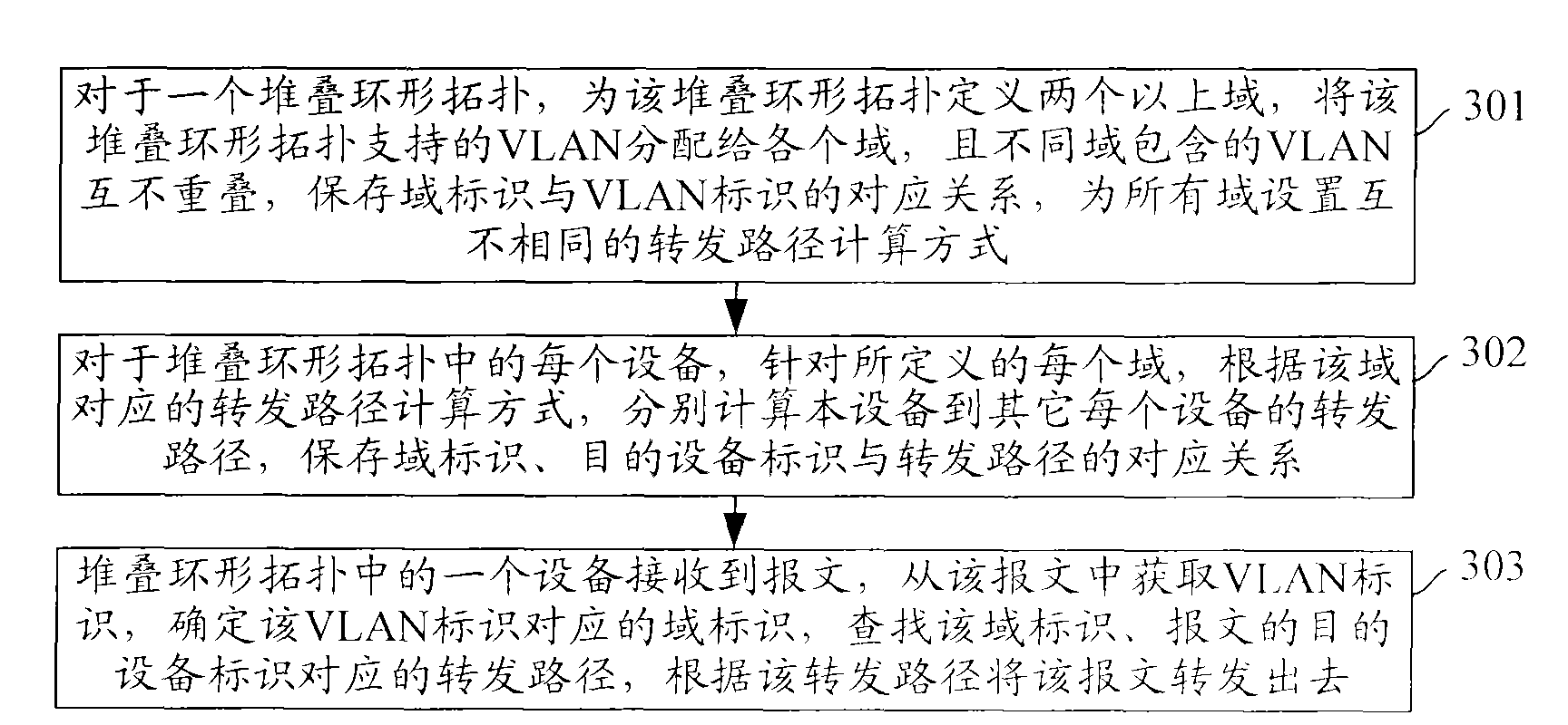
[0044] image 3 The flow chart of the load sharing method under the stacking ring topology provided by the embodiment of the present invention, such as image 3As shown, the specific steps are as follows:

[0045] Step 301: For a stacking ring topology, define more than two domains for the stacking ring topology, assign the virtual local area network (VLAN, Virtual Local Area Network) supported by the stacking ring topology to each domain, and the VLANs contained in different domains are different from each other. Overlap, save the corresponding relationship between domain ID and VLAN ID, and set different forwarding path calculation methods for all domains.

[0046] It can be seen that each domain contains at least one VLAN, and each VLAN uniquely belongs to one domain.

[0047] Step 302: For each device in the stacking ring topol...


PUM


Abstract

The invention discloses a load sharing method and load sharing equipment for stacked ring topology. More than two domains are defined for the stacked ring topology. All virtual local area networks (VLAN) supported by the stacked ring topology are allocated to each domain, and the VLANs in each domain are not overlapped with one another. Different forwarding path calculation ways are set for each domain. The method comprises the following steps of: for each defined domain, calculating forwarding paths of each piece of equipment to other equipment in the stacked ring topology in the domain according to the forwarding path calculation way corresponding to the domain; and when any piece of equipment in the stacked ring topology receives a message, determining the domain corresponding to the VLAN of the message, and forwarding the message according to the forwarding path of the equipment receiving the message to the destination equipment of the message in the domain corresponding to the VLAN of the message by using the equipment receiving the message. By the method and the equipment, he load sharing in the stacked ring topology is realized, and the bandwidth utilization rate is increased.

Description

technical field [0001] The invention relates to the field of stacking technology, in particular to a load sharing method and equipment under a stacking ring topology. Background technique [0002] Early Cisco (Cisco) Catalyst 6500 series switches only supported stacking of two chassis to form a virtual switching system (VSS, Virtual Switching System), such as figure 1 shown. Through this stacking system, the switching capacity of the whole machine can be increased to 1.44T. The active virtual switch and the standby virtual switch are connected through a virtual switching link, and are connected to the aggregation layer or access layer device through cross-device aggregation, combined with distributed switches The use also has the following advantages: [0003] 1. As a device, the stacking system increases the port density of the system and simplifies the management methods; [0004] 2. Through stack port aggregation and cross-device aggregation, load sharing and link back...

Claims


Application Information

Patent Timeline
Patent Type & Authority Applications(China)
IPC IPC(8): H04L12/56H04L12/46H04L45/02H04L45/122
Inventor 王明辉
Owner NEW H3C TECH CO LTD
Why Eureka
Try Eureka