Valve timing control apparatus

A technology of valve timing control and timing sprockets, applied in valve devices, engine components, machines/engines, etc., can solve problems such as low feasibility

Inactive Publication Date: 2011-07-13
AISIN SEIKI KK
View PDF6 Cites 12 Cited by
  • Summary
  • Abstract
  • Description
  • Claims
  • Application Information

AI Technical Summary

Problems solved by technology

However, the extent of masking used for processing, and the complex processing used for surface treatment, result in lower viability

Method used


Image

  • Valve timing control apparatus
  • Valve timing control apparatus
  • Valve timing control apparatus

Examples


Embodiment Construction

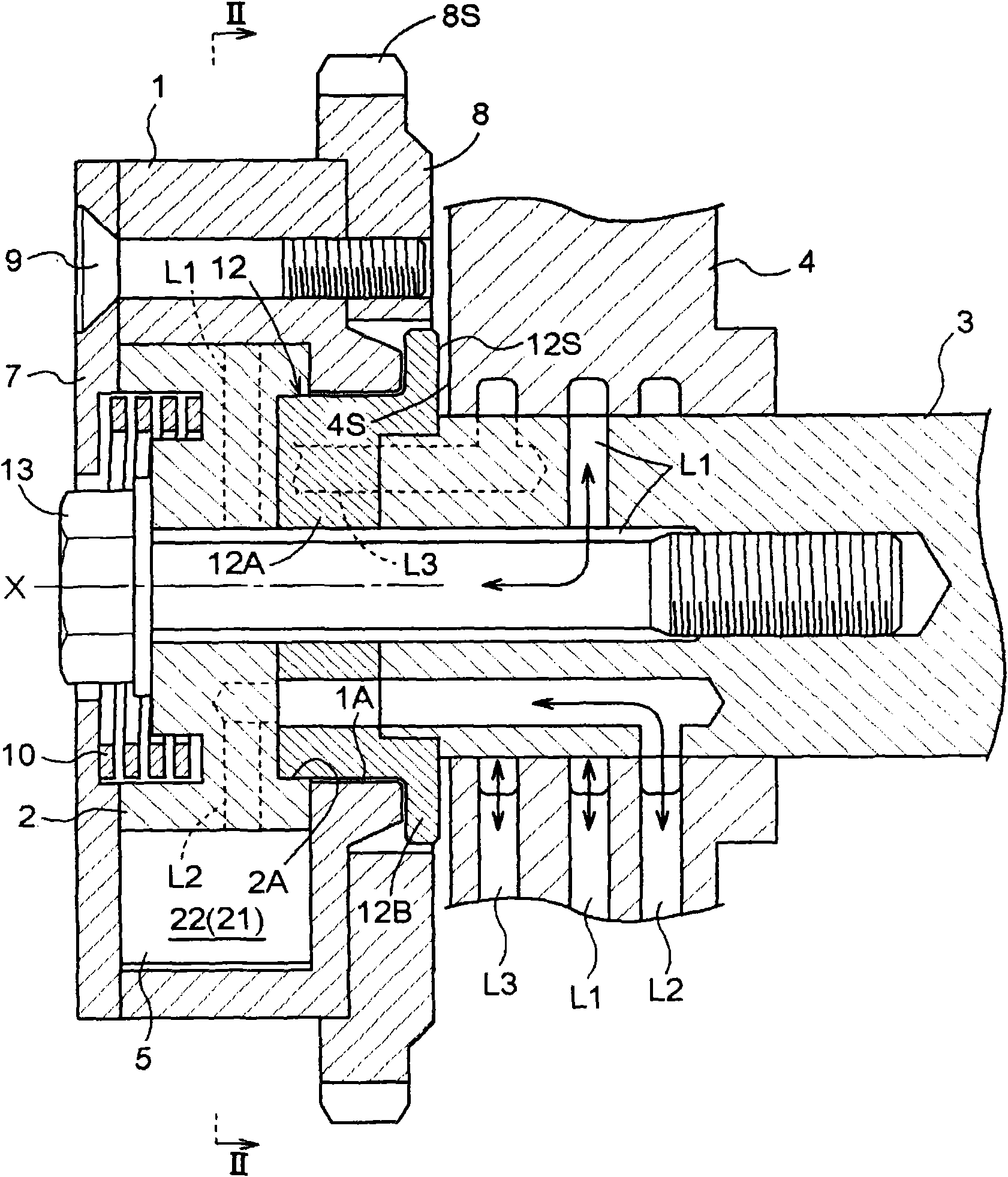
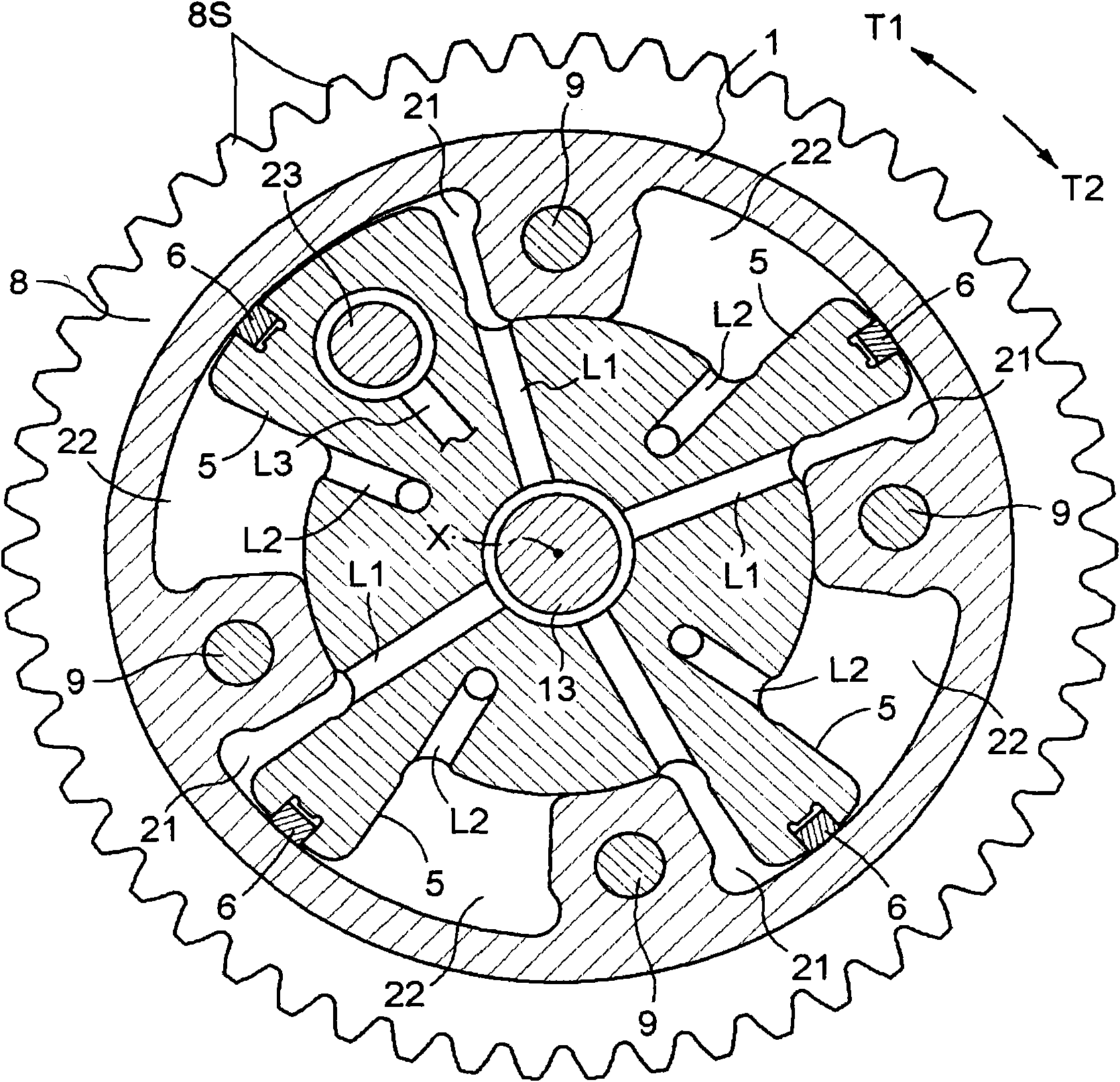
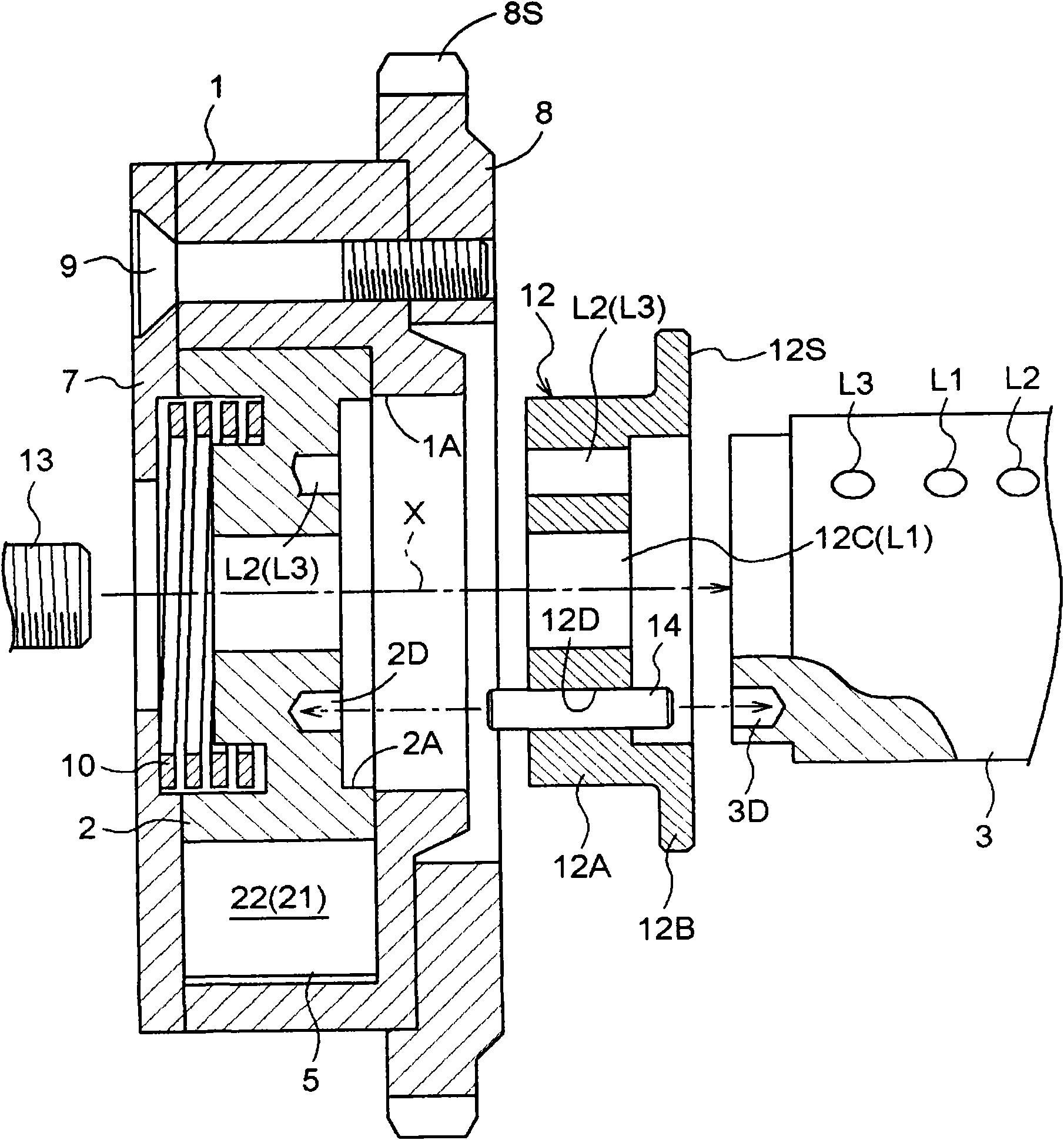
[0027] Embodiments disclosed herein are described with reference to the drawings. Such as figure 1 and figure 2 As shown, the valve timing control apparatus according to the present embodiment includes an outer rotor 1 as a driving side rotating member, an inner rotor 2 as a driven side rotating member, a retarded angle chamber 21 , and an advanced angle chamber 22 . The retarded angle chamber 21 and the advanced angle chamber 22 constitute and serve as a rotational phase adjustment device, by operating the supply and discharge of oil from the electromagnetic control valve relative to the retarded angle chamber 21 or the advanced angle chamber 22, to change or adjust the outer rotor 1 and the inner rotor. The relative rotational phase between 2. Via a timing chain, the outer rotor 1 rotates in a synchronous manner with the crankshaft of the engine, ie the internal combustion engine. The inner rotor 2 integrally rotates together with a camshaft 3 that opens or closes an int...


PUM


Abstract

A valve timing control apparatus includes a drive-side rotation member (1) synchronously rotating with a crankshaft of an internal combustion engine (4), a driven-side rotation member (2) integrally rotating with a camshaft, a rotational phase adjusting device including a retarded angle chamber (21) and an advanced angle chamber (22), the rotational phase adjusting device adjusting the relative rotational phase between the drive-side rotation member and the driven-side rotation member, and a boss member (12) provided at a portion of the driven-side rotation member (2) facing an outer wall surface (4S) of the internal combustion engine (4) and including a thrust surface (12S) that extends to be perpendicular to a rotational axis (X) of the camshaft (3) and that is exposed to the outer wall surface (4S) of the internal combustion engine (4). The boss member causes the drive-side rotation member to be prevented from making contact with the outer wall surface by making contact with the outer wall surface of the internal combustion engine.

Description

technical field [0001] The present invention relates to a valve timing control device installed on the outer end of a camshaft to adjust the opening and closing timing of an intake valve or an exhaust valve of an internal combustion engine applied to a vehicle such as a motor vehicle. More particularly, the present invention relates to a technique for supporting a valve timing device. Background technique [0002] A technique for supporting a valve timing control device is disclosed in US 6,176,210 B1 (hereinafter referred to as Patent Document 1). The valve timing control device disclosed in Patent Document 1 includes a drive-side rotary member integrally rotated with a sprocket to which a rotational driving force of a crankshaft is transmitted via a chain. A bearing portion is integrally formed at the driving side rotating member. The valve timing control device further includes a driven side rotating member, and the rotational phase of the driven side rotating member re...

Claims


Application Information

Patent Timeline
Patent Type & Authority Applications(China)
IPC IPC(8): F01L1/344
CPCF01L1/3442F01L2001/0476F01L2001/34483
Inventor 野口祐司本间敦朝日丈雄
Owner AISIN SEIKI KK
Why Eureka
Try Eureka